FishEye |

|

|

|

|

|
||
|
FishEye |
|
|
|

|

|

|
FishEye
|
FishEye |
|
|
|
|
|
||
|
FishEye |
|
|
|
|
|
|
|
|
||
Graphics window Toolbar
Fisheye |
|
A camera with a field of view in the form of a part of a sphere (fisheye, panoramic 360°/180°).
The ability to independently set the circular angle of view of the lens, the limitations of the field of view on the size of the video sensor, the aspect ratio of the frame, and the mapping function allows you to simulate a variety of wide-angle cameras with angles up to 250 degrees using the Fisheye parametric model.
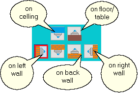
On the Camera Position panel, in the Hor. angle, Tilt angle, and Axial rotation angle sets the angles of rotation of the main optical axis of the Fisheye camera in the horizontal and vertical planes, as well as the angle of rotation of the camera around the main optical axis.
So, if the camera is installed on a vertical wall, then the Tilt angle should be equal to zero, and the Hor. angle is determined by the orientation of the wall. If the camera is mounted on a ceiling, then the Tilt angle must be 90 degrees, and the Hor. angle does not matter. If the camera is installed on the floor, the Tilt angle should be -90 degrees.
Below are buttons for conveniently assigning angles to 6 typical camera positions.
Rotation, tilt and rotation around its own axis, set in the usual way in the Graphics window and the Camera Geometry box, do not affect the position of the Fisheye camera.
You can change the direction of the optical axis of Fisheye cameras in space by shifting the image with the mouse in the 3D Video window with the left button pressed, just like it is implemented for conventional cameras. The rotation angle of the Fisheye camera around its own axis can also be changed in the 3D Video window by rotating the image with the mouse with holding Shift.
|
Circular FOV angle of the Lens
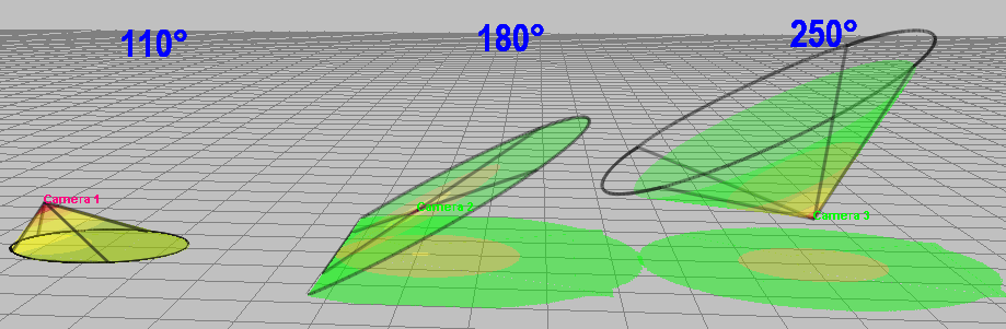
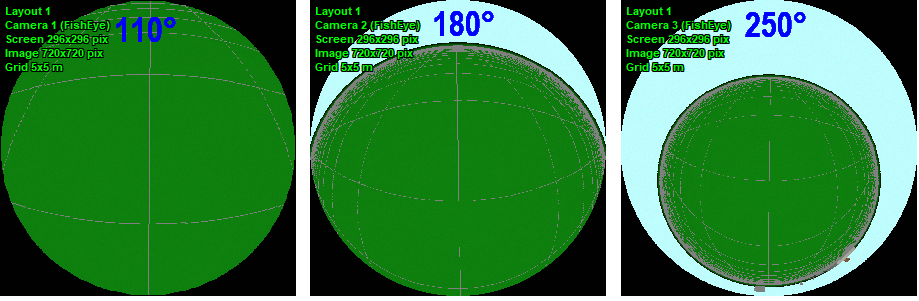
The maximum circular view angle of a Fisheye lens can be set in the range of 110-250 degrees. Thus, it is possible to simulate both narrow-angle and ultra-wide-angle Fisheye cameras. A typical value for this angle is 180°, but there may be other values.
|
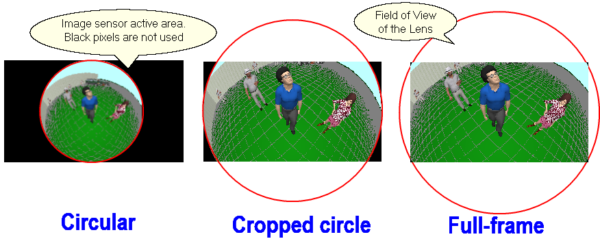
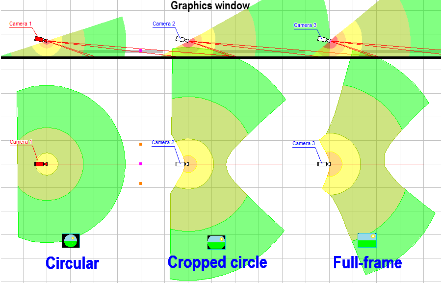
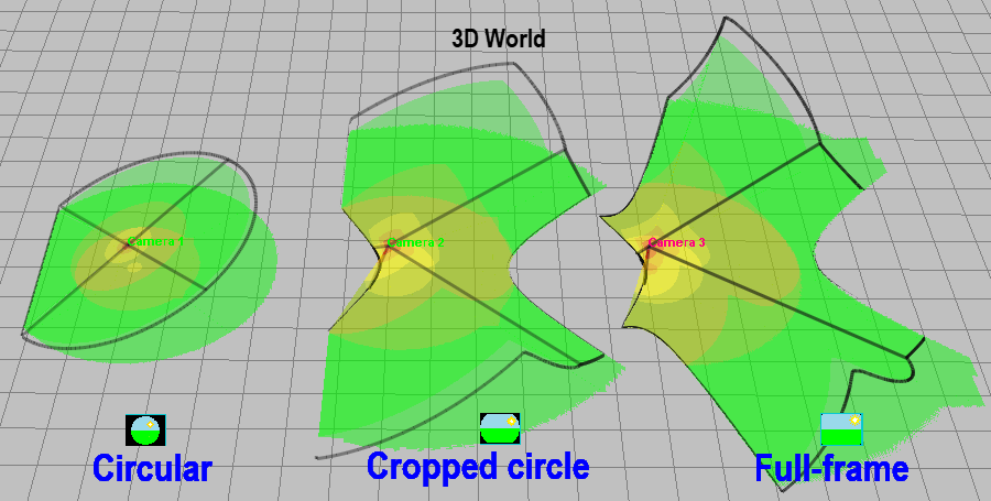
The circular field of view of a FishEye lens can be limited by the image sensor. Depending on this limitation, there are 3 types of FishEye lenses: Circular and with limited field of view (Cropped circle and Full frame).
Fisheye cameras with limited field of view allow you to use the image sensor more fully. With the same image sensor, Fisheye cameras with limited field of view can double pixel density at a given distance (for a 16:9 sensor) or, at a given pixel density, increase the distance up to 2 times compared to Fisheye cameras with circular field of view. The cost of this improvement is a slight loss of vertical and/or horizontal field of view.
By setting the Sensor limit View angles, any of the three types of Fisheye lenses and their intermediate variants can be simulated.
You can simply switch the lens type using the buttons, the angles of view for the current aspect ratio will be calculated automatically.
If the button remains pressed, when changing the aspect ratio, VideoCAD will recalculate the angles to save the selected lens type for the new aspect ratio. To prevent the angles from being recalculated, release all the buttons.
The view angles of Fisheye cameras with a field of view limited by the image sensor (Cropped circle and Full frame) depend on the Mapping function.
The view angles of real lenses may differ from the mathematical model, so if you know the angle values from the camera specifications, it is better to enter them in the appropriate boxes and release all buttons so that VideoCAD models the camera according to the real view angles.
For one camera, you can set different view angles for different aspect ratios / resolutions through the List / Range of Lens focal lengths.
|
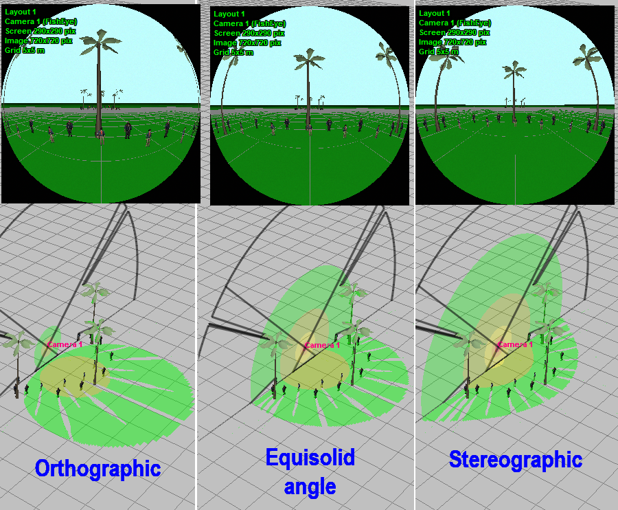
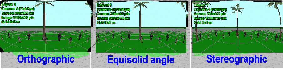
Accounting for the Mapping function is not mandatory, it only allows you to increase accuracy of modeling of Fisheye lenses when necessary. If you do not have information about the Mapping function, then set the Equisolid angle.
The Mapping function determines the distribution of the pixel density of the image sensor between the center and edges of the field of view and depends on the internal construction of the lens.
See more about the Mapping function in Wikipedia
It is important that for Fisheye cameras with the field of view limited by the image sensor (Cropped circle and Full frame) the Mapping function determines the view angles.
In VideoCAD13 all types of Mapping function are fully modeled in the 3D Video and 3D World window. In the Graphics window, the Mapping functions are modeled when constructing the shape of view area projections, and when distributing the pixel density the Equisolid angle function is used.
The ability to independently set the circular angle of view of the lens, the limitations of the field of view on the size of the video sensor, the aspect ratio of the frame, and the Mapping function allows you to simulate a variety of wide-angle cameras with angles up to 250 degrees using the Fisheye parametric model.
In the 3D World, for Fisheye cameras of any type, the view area border is now drawn when the Fisheye>Show>Full image item is selected on the Image parameter panel, Panoramic tab.
|
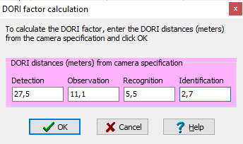
The DORI distances (Detection, Observation, Recognition, Identification) in the specifications of most camera manufacturers are close to the values calculated by VideoCAD and do not need adjustment. However, in reality, the resolution at the edges of the field of view may be worse than the resolution in the center of the field of view, which is more pronounced in high-resolution Fisheye cameras. To take into account the decrease in resolution at the edges of the field of view, several manufacturers provide in the specifications specially reduced values of DORI distances for the case of installing the camera on a low ceiling (~3m), since in this position the edges of the field of view determine the DORI distances. To take into account a possible reduction in resolution, the DORI factor has been added to the parameters of FishEye cameras in VideoCAD. The factor can be set in the range of 0.5.1 separately for each camera, which ensures that different Fisheye cameras are modeled exactly according to the DORI distances in their specifications.
The default value of the DORI coefficient is 1, that is, the resolution of FishEye cameras is considered the maximum. According to BOSCH, when installing a camera on a low ceiling, it is recommended to reduce the coefficient to 0.5-0.6 for 12MP cameras. HIKVISION provides DORI distances taking into account the same resolution reduction factor.
The DORI factor is not explicitly given in camera specifications, there is only a DORI distances. Therefore the DORI string with the DORI distances via space has been added to the parameters of camera models, from which the DORI Factor is automatically calculated when assigning a model to the active camera.
The
The DORI factor adjusts the FishEye camera resolution in all program windows, not just when displaying the Pixel Density.
The DORI factor =1 corresponds to the absence of resolution correction.
|
Pixel density of Fisheye cameras
Image resolution of a Fisheye camera is determined by the Number of pixels of sensor Lens focal length and Image size at image processing have no affect on the image resolution of a Fisheye camera.
Pattern criterion of pixel density for panoramic cameras must be based on pixel density (Pixel per meter (Pixel per foot), Pixel for object), but not on field of view size. Criterion Field-of-view height, % of Field-of-view for object are not suitable to panoramic cameras, because of panoramic cameras don't have a stable field of view. The Vert.(Horiz.) number of pixel box displays a virtual number of pixels for correct simulation of the resolution..
|
Fisheye in the Graphics window and 3D World
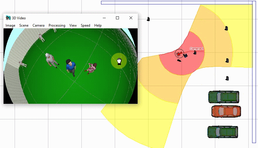
In the Graphics window, the horizontal projection of the view area is modeled and the pixel density distribution of the PTZ cameras is visualized. The projection is constructed according to the rule Within projection.
In the 3D World the camera coverage area and distribution of pixel density are visualized.
The maximum drawing distance of view area projections is determined by the Maximum distance of drawing view area.
To draw a camera using the special icons
The lens focal length boxes in the Graphics window and the Camera Geometry box for panoramic cameras, as well as the button on the Toolbar are colored by aqua In reports and in the exported dxf or dwg files for panoramic cameras instead of the lens focal length value the 'fisheye' word is displayed.
|
Fisheye camera in the 3D Video window
In the 3D Video window, VideoCAD can simulate 3 types of image from Fisheye cameras:
You can switch image type on the Panoramic tab of the Image parameter panel.
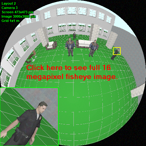
It may take some time to generate the full image, please wait.
The full fisheye image mode supports PiP mode, motion simulation, animation, lens resolution, and partial sensitivity modeling. In the Full Image mode with PiP enabled, you can generate a combined image of the full 360/180 image with screen resolution and a superimposed fragment with real camera resolution.
The Real frame size option allows you to generate the full image from Fisheye cameras with real camera resolution exceeding screen resolution. Images from Fisheye cameras with resolutions of tens of megapixels can be modeled as a whole, as well as images from usual megapixel cameras.
In the Full image mode, you can change the rotation and tilt of the Fisheye camera by moving the picture with the mouse while holding down the left button. Hold Shift to rotate the camera around its axis. In the Image Fragment mode, you can change the position of the image fragment in the same way.
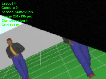
Dewarped image fragment with real camera resolution
By rotation the camera in the usual way in the Graphics window, Camera Geometry and 3D Video, you can view images from the Fisheye camera in different directions in the 3D Video. In this case, the view area will be limited by the Circular angle of the lens. Beyond this limit the image is cut.
Image resolution of a Fisheye camera is determined by the Number of pixels of sensor Lens focal length and Image size at image processing have no affect on the image resolution of a Fisheye camera.
You can change the Lens focal length, thereby changing the field of view size, but the image resolution in the 3D Video will be always maintained equal to the calculated resolution of the Fisheye camera. If the calculated resolution is worse, the resolution of the 3D Video will be artificially reduced. If the calculated resolution is better, then the PiP mode will be launched in the 3D Video. The Image line in the Titles displays a virtual number of pixels for correct simulation of the resolution. In the Dewarped fragment mode distortion of a Fisheye camera images in the 3D Video is not modeled. The simulated resolution is exact only at the center of the frame. Towards the edges of the frame the actual resolution is worse than simulated. The smaller the view angle, the more accuracy of simulating resolution on the edges of the frame. For a more realistic model of the image, turn on modeling compression and smoothing, or set the actual resolution of the lens (for accurate simulation the lens resolution you also need to specify the correct size of the image sensor).
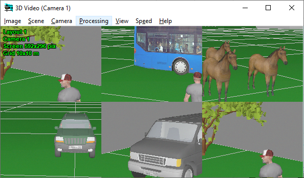
Several fragments from Fisheye camera on one image
You can save the camera positions corresponding to the fragments of the image as camera positions and get these fragments on one image in the screen division mode. The resolution of each fragment on the multi-image will be limited by resolution of the Fisheye camera.
To enable displaying positions as fragments of Fisheye camera, select Positions> Show> Positions and Fisheye> Show> Dewarped Image Fragment on the Panoramic tab of the Image Parameter Panel.
See more.Positions of active camera
|
To make a camera model a Fisheye camera it is necessary:
For one camera, you can set different view angles for different aspect ratios / resolutions through the List / Range of lens focal lengths. You can set the Mapping function.
|
See also: Modeling Fisheye cameras,Positions of active camera