|
|


|

|

|

|

|
|||
|
Table of camera models Parameter description |
|
|
|

|

|

|
|
|
|
|
|
|
|
|
|||
|
Table of camera models Parameter description |
|
|
|
|
|
|
|
|
||
The red highlighted parameters are used in camera modeling. The rest parameters exist only for information and comparison of different models. The majority of parameters can be chosen from lists.
Unique model number in the base of models. At the moment of new model creation the number is generated automatically. The Number is a service column it is not visible by default.
|
The Label field allows you to mark models with custom labels (eg OK, BAD, Order, In stock, Used, Outdated..). You can filter models by labels, as well as by any other table fields and their combinations.
|
Model name.
|
Manufacturer of the model.
|
The name of a series in the manufacturer's catalog to which the model belongs.
|
Key features of the model.
|
Photo of the camera model. The cell has a drop-down menu for saving, loading, copying, and pasting photos.
By clicking on the cell, you can call up the Camera model card window for more detailed viewing of photos. The window dynamically displays photo from the selected row of the table.
See also: Camera model card,
|
Output type of camera.
|
B/W (black&white), color, day/night (removable IR filter) easy day/night (permanent IR filter). At illumination reduction day/night and easy day/night cameras are switched into black-white mode.
Color parameter influences 3D model color as well as spectral sensitivity of cameras to various light sourses.
See more: Color
|
The cell is designed to store the features of the network capabilities of the camera.
|
An Icon by which the camera will be drawn in the Graphics window.
The icon type is influenced by Protection parameter as well.
|
Image sensor model. If ExView HAD ™ CCD is chosen, in calculation of illumination from different light sources special factors will be used, considering increased relative IR spectral sensitivity of such image sensor.
See also: ExView
|
The Size parameter determines size of the image sensor or size of active area of the image sensor.
See more: Image Sensor and Active area of image sensor
The Image sensor size can be specified by any of the following ways:
After format or length of diagonal, separated by space, you can specify the aspect ratio of the image sensor in the form of W:H. For example: 1/3" 16:9 or d6 16:9. If the aspect ratio of the image sensor is not specified, it is assumed equal to 4:3.
Active area size of the image sensor can be specified in millimeters horizontally and vertically via asterisk, in the form of W*H. For example: 4.8*3.6;
See also: Image sensor size, Specifying active area size of the image sensor
|
Horizontal and vertical numbers of active pixels of the image sensor. Number of pixels is used in modeling image resolution and in calculation of person detection, identification and license plate reading areas. Number of pixels of output image are set separately and can differ from the numbers of effective pixels of the image sensor.
See also: Number of pixels, Active pixels, List of resolutions
|
Using the List/Range and the List of Resolutions, you can model complex dependences of view angles on the aspect ratio, resolution and the lens focal length of a camera model.
The List of resolutions contains a list of possible resolutions of the camera model in pixels. The user can select the resolutions of the active camera from this list.
In addition, each resolution in the list can be assigned the Crop factor of reducing the size of the image sensor.
It is also possible to automatically calculate the Aspect ratio from the ratio of the numbers of pixels horizontally and vertically.
Thus, by the List of resolutions it is possible to describe the dependence between the selected resolution in pixels and the size of the active area of the image sensor.
If the List / Range and List of Resolutions strings are specified in the camera model parameters, the user only needs to select the lens focal length and resolution from the drop-down lists to obtain accurate model of camera's view area, taking into account lens distortion and dependence of active area size of the image sensor from the resolution.
For the convenience of filling the List of resolutions, the cell has a special drop-down form.
See more: List of resolution.
|
Aspect Ratio of the output image (horizontal side size of the output image to the vertical side size): 4:3, 16:9 etc. The Aspect ratio of the output image may be different from the Aspect ratio of the image sensor (can be specified in the Size field).
See more: Specifying the Aspect ratio on output image
You can enter custom values from keyboard in the form of <width> :<height>, for example 11:4.
By specifying formats 3:4 or 9:16, you can set the so-called corridor format in which the height of the frame is larger than its width.
For correct simulation resolution in the corridor format you must also swap the number of pixels horizontally and vertically in the camera parameters and image processing settings.
Via space character after the Aspect ratio you can set the crop factor - the ratio of cropping active area size of the image sensor when the active area does not touch the edges of the image sensor. Crop factor can be set as a vulgar fraction (separated by slash) or a real number. For example 4:3 0.67 or 16:9 720/1080. If the crop factor is not specified, it is taken to be unity.
If Yes is selected in the Calculate from pixels cell, then the Aspect ratio of the camera of this model will always be equal to the ratio of the numbers of pixels horizontally and vertically.
See also: Specifying the crop factor, Aspect ratio, Specifying active area size of the image sensor
|
Whether the corridor mode is possible for this camera model. If the Corridor mode is possible, the buttons In the Corridor mode, the camera rotates 90 degrees around the optical axis, the horizontal and vertical of the field of view are reversed.
Values <4MP, <1920/1080.. set the maximum number of pixels at which the corridor mode is operable. If more pixels are assigned to the camera, a warning will be shown when corridor mode is enabled.
|
Interlaced or progressive. Analog cameras always have interlaced scan. Digital cameras can have progressive scan. Progressive scan is preferable.
Modeling interlace distortion can be enabled separately in camera parameters. This parameter of camera model does not affect the simulation of interlace scan .
See also: One field, Interlace
|
This parameter is used for modeling distortion of moving 3D models and rotating Rotakin object arising from the Rolling Shutter effect.
As a result of Rolling Shutter work, exposure of different rows of the image sensor begins and ends sequentially at different times, which causes a horizontal shift of moving objects. This effect occurs with many IP cameras with CMOS image sensor and doesn't occur with cameras with CCD image sensor.
Row time (microsecond) is the time period (in microsecond) between the beginning of exposure of adjacent rows. Unfortunately this parameter is not given in the cameras' specification. To elucidate the value of the parameter you should contact the manufacturer or measured this time in practice.
See also: Rolling Shutter
|
This switch deternines direction of scanning strings by the Rolling shutter. Top-down or Down-top.
See also: Rolling Shutter
|
Resolution of the camera, in LPH. At 3D modeling image resolution will be limited up to the value set in this field.
If N/A is chosen in the field, then resolution limitation is disabled.
Items sharp+1, sharp+2, sharp+3 on the contrary increase image sharpness. With the help of these items it is possible to model effect of Aperture corrector.
Aperture corrector is automatically switched-off at insufficient illumination.
See also: Resolution
|
In the Contrast % you can specify a drop of contrast in % according to the MTF at the specified number of lines LPH.
|
If Yes is set then only horizontal resolution is modeled, which is typical for analog cameras. If NO is set, the camera resolution will decrease horizontally and vertically in the same degree.
|
Maximal frame rate with max resolution (fps)
Many of megapixel cameras have limits of frame rate, which depends on image number of pixels.
When assigning a frame rate to a camera that is higher than the maximum frame rate, the frame rate window turns pink, but the assignment itself is not prohibited.
See also: Frame rate
|
Signal/noise (Max, dB, weighted)
Maximum signal/noise ratio. Unweighted value.
See more: S/N max. |
Sensitivity
Sensitivity of cameras is modeled only in VideoCAD Professional
Digital control of modern cameras can significantly increase the signal-to-noise ratio at the cost of losses in overall resolution or resolution of moving objects. But the signal-to-noise ratio is used as a criterion of image quality when measuring the minimum illumination (sensitivity) of a camera.
If 2D and 3D noise reduction (2DNR 3DNR) mode and / or Pixel Binning are turned on in a camera, the result of measuring the minimum illumination may be several times less than when the digital control of the camera is turned off.
However, 2D noise reduction improves the appearance of an image, but does not increase its informativeness. 3D noise reduction reduces noise only on fixed objects. Pixel Binning leads to a deterioration in the overall resolution in several times. In case of inattentive examination, these image defects can be overlooked.
For correct assessment and comparison of sensitivity, the Camera sensitivity mode parameter may contain a short description of the operation mode in which the camera shows the claimed minimum scene illumination value.
See also: Camera sensitivity mode
|
In VideoCAD it is meant, that scene reflection factor is 0.75, light source - halogen incandescent lamp (color temperature 3100 +-200K) according to Standard CEA 639 'Consumer Camcorder or Video Camera Low Light Performance'.
For day/night and easy day/night cameras, 2 minimum illumination values can be used: in color and black and white modes.
If only the illumination value in black/white mode is specified, then the value in color mode is assumed to be:
If only the illumination value in color mode is specified, then the value in black/white mode is taken equal to:
Parameter Color>B/W swithing S/N defines the signal-to-noise ratio at which the day/night and easy day/night cameras switch to black and white mode.
For unambiguous description of sensitivity in VideoCAD, should be pointed also:
In VideoCAD the minimum illumination is specified at maximum exposure time.
See more: Min. illum. (lx), Camera mode |
AT:
Exposure time (milliseconds) at which the minimum illumination has been measured. Parameter is sometimes given in camera specifications. For analog cameras typically value is 20ms (PAL) or 16.5ms (NTSC). For IP cameras and analog cameras with light accumulation the exposure time may be up to 200ms or more.
At modeling the exposure time assumed the truth of the Reciprocity principle, that is inversely proportional of sensitivity to the exposure time.
See also: at exposure (ms), modeling exposure.
|
Lens aperture at which the minimum scene illumination is measured. The parameter is given in camera specification. Typical value from F1.0 up to F2.0.
|
Signal/noise ratio of the image at the minimum illumination, unweighted value.
According to CEA 639, limit value of signal/noise ratio at the minimum illumination determination is 17dB (7 times in voltage).
|
IRE of video signal at minimum illumination, at AGC switched on by default.
In VideoCAD 100 IRE corresponds full peak-to-peak amplitude of video signal and accordingly to maximum brightness amplitude on the image. 50IRE corresponds half of maximum brightness amplitude on the image, etc.
The parameter is given in camera's specification. Typical value is from 30 to 50.
|
The signal-to-noise ratio of the simulated image, upon reaching which, as a result of a decrease in illumination, the day/night and easy day/night cameras switch to black/white mode.
|
Exposure time limits within which electronic shutter operates.
The parameter is given in camera's specification. For IP cameras the maximum exposure time can be up to several seconds.
To set the maximum exposure to more than 1 second, enter a value with a dot, for example: 2 = 1/2 second; 2.0 = 2 seconds.
See more: AESC |
In this cell it is possible to specify Maximum AGC gain (dB) for cameras with switchable AGC gain: High AGC gain (High AGC, S-AGC, Super AGC) or LO AGC gain. The box will be enabled and the set AGC limit will be considered in modeling, if the Set box is marked. Enter in the cell maximum AGC gain if it is given in the camera's specification.
Typical value is 26-42dB.
If the camera does not have switchable AGC gain, the maximum AGC gain is calculated by the program.
See also: AGC
|
The parameter is given in cameras' specification. Normally gamma correction degree equals 0.45. The degree equal 1 is equivalent to absence of gamma correction.
See more: Gamma
|
The camera model has a built-in illuminator.
You can set: IR wavelength (nm) or select White LED, optical radiated power (W) or luminous flux for white LED, the full angle of the radiation cone. If parameter = Max. view angle is set, the radiation angle is assigned equal to the maximum of the view angles; Concentration is the ratio of the radiation intensity at the edge of the radiation cone to the radiation intensity along the axis of the radiation cone. Max. distance is the maximum distance of the IR illuminator. This parameter can be assigned to the camera from camera model parameters or calculated from parameters of the IR Illuminator and camera sensitivity. To correct simulation of the expected image in 3D and calculation of the Max. distance, the camera sensitivity must be set correctly.
In most real camera specifications, objective parameters of the built-in illumination are not given and we can only use the subjective Maximum Distance.
See more Built-in IR illuminator, Modeling Built-in IR illuminator |
Compatibility Protocol of IP cameras with other equipment.
|
Information about Wide Dynamic Range.
|
Supported types of compression.
Modeling compression can be enabled separately in camera parameters. This parameter of camera model does not affect the simulation of compression.
See also: Compression
|
Supported types of noise reduction.
|
Information about IP Camera traffic encryption.
|
Any other features of image processing inside of camera.
|
Connectors (sockets, input-output, I/O)
Presence or absence of various purpose connectors on camera case. |
Possibility of switching OFF/ON of electronic shutter and specifying its limits. The parameter determines accessibility of shutter parameters changing in the Sensitivity and Resolution box for a camera of this model.
|
Possibility of switching OFF/ON of AGC and specifying its limits. The parameter determines accessibility of AGC parameters changing in the Sensitivity and Resolution box for a camera of this model.
Low/high value corresponds to availability of AGC gain switch. AGC gain value in this case is specified by AGC parameter AGC (dB, max).
|
Possibility of switching OFF/ON of Gamma correction and specifying its degree. The parameter determines accessibility of Gamma parameters changing in the Sensitivity and Resolution box for a camera of this model.
|
Possibility of switching OFF/ON of Auto iris DC and specifying its level. The parameter determines accessibility of Auto iris DC changing in the Sensitivity and Resolution box for a camera of this model.
|
Possibility of switching OFF/ON of Back light compensation and specifying its type. The parameter determines accessibility of BLC parameters changing in the Sensitivity and Resolution box for a camera of this model.
|
Any other switches and adjusments.
|
Presence and type of remote control feature. |
Name of lens model.
|
Lens format must be no less than camera sensor format.
|
Lens mount type.
|
Lens type.
Prior to VideoCAD13, selecting fisheye could enable camera simulation with a FishEye lens. Starting with VideoCAD13, FishEye simulation is enabled by selecting fisheye in the Distortion>Model. / Fisheye field.
|
Lens infra-red correction. IR corrected lenses don't shift focus between normal scene illumination and IR illumination. |
Focal length control type. For fixed focal length, changing focal length is locked for camera of this model.
|
Current lens focal length in mm.
See also: Lens focal length, List/Range
|
Using the List/Range and the List of Resolutions, you can model complex dependences of view angles on the aspect ratio, resolution and the lens focal length of a camera model.
The lens focal length in VideoCAD is specified by one current value and additionally by the List / Range string. Depending on type of the lens, the List / Range string may contain: • the list of possible focal lengths; • the range of possible change of the focal length; • the list of possible focal lengths with values of real angles for modeling lens distortion; • the range of possible change of the focal length with the values of real angles for modeling lens distortion.
If modeling distortion is not used, the List / Range string can only set limits of the lens focal length by a list or a range. But if the List / Range string includes the values of real angles, the string allows to accurately describe the relationship between the focal length values and viewing angles, taking into account the lens distortion.
If correct List / Range and List of resolutions are specified in the camera model parameters, the user can just select the camera model, lens focal length and resolution in pixels from the drop-down lists to get the exact model of the camera's view area.
For convenience of filling the List / Range the cell has a drop-down form.
See details: List/Range of Lens focal lenght, Lens focal length
|
Calculated angles of view of the lens. Angles of view are determined by VideoCAD, from camera sensor size and lens focal length.
In the List / Range cells, the calculated angles for focal lengths from the List / Range string are displayed.
Real angles of view can differ from the calculated ones because of Lens distortion
|
Iris control type. For fixed iris, changing aperture is locked for camera of this model.
See also: Iris type
|
Open WIDE (F), Open TELE (F), Closed (F-number)
The larger the F-number is, the smaller the aperture and less light passing through the lens. With varifocal lenses, the aperture at maximum focal length is usually smaller than the aperture at minimum focal length.
During camera simulation, the open aperture of a varifocal lens is calculated from WIDE to TELE depending on the current focal length of the lens. In the case of auto auto iris simulation, the current aperture is calculated in the range from open to closed.
See also: Aperture limits
|
Minimum distance on which the lens can be focused.
|
Automatic focusing. This function can be found in cameras with built-in lens. |
Resolution of the lens in line pairs per millimeter (lp / mm). Lp / mm - is the number of pairs of lines (black + white line) perpendicularly intersecting a segment on the image sensor of length of 1 millimeter. Note the difference with the unit of camera resolution, LPH. Resolution of cameras is measured in the amount of black and white lines, but the lens resolution is measured in line pairs , that is, at the same actual resolution, the lp / mm value is in 2 times less than LPH.
Effect of lens resolution on the final resolution of the camera depends on the ratio of lens resolution in lp / mm to the number of pixels on the image sensor per 1mm (pixel density on the sensor) . Thus, the smaller the size of the image sensor is and the more pixels on it - the higher lens resolution must be in order that the lens does not spoil the resolution of the camera .
In the 3D Video window image resolution will be limited by values in these boxed. If N/A is chosen, then the lens resolution limitation is disabled.
You can also simulate the camera resolution. When the lens resolution simulation and camera resolution simulation are both enabled, then their effects are summarized.
You can check resolution visually using the Test chart.
|
In the field you should enter contrast drop in % according to MTF (Modulation Transfer Function) at the specified value of lp/mm.
|
Lens distortion simulation control or enable FishEye camera simulation
See also: Real angles
|
Lens distortion is defined by the values of the calculated and real view angles ( horizontal, vertical , diagonal ) . The calculated angles are obtained by calculating from the focal length and the image sensor size (format). The real angles are usually given in the specifications of cameras and lenses. If the real angle is unknown, you can get them by practical measuring.
If the column Set Calc is present, then this angle is not set, it will be calculated by the program, if there is Set, the corresponding real angle must be specified.
If the Distortion/FishEye>Model/FishEye parameter is set to fisheye, then the horizontal and vertical real angle values determine the angles of view of the sensor, and the diagonal angle determines the FishEye camera's circular angle of view .
To set the Real angles separately for multiple lenses and resolutions, as well as the Real angles for varifocal lenses, use the List/Range of Lens Focal Length.
See more: Lens distortion See also: List / Range, FishEye
|
FishEye lens specific parameters.
See also: FishEye
|
The DORI distances (Detection, Observation, Recognition, Identification) in the specifications of most camera manufacturers are close to the values calculated by VideoCAD and do not need adjustment. However, in reality, the resolution at the edges of the field of view may be worse than the resolution in the center of the field of view, which is more pronounced in high-resolution Fisheye cameras. To take into account the decrease in resolution at the edges of the field of view, several manufacturers provide in the specifications specially reduced values of DORI distances for the case of installing the camera on a low ceiling (~3m), since in this position the edges of the field of view determine the DORI distances. To take into account a possible reduction in resolution, the DORI factor has been added to the parameters of FishEye cameras in VideoCAD. The factor can be set in the range of 0.5.1 separately for each camera, which ensures that different Fisheye cameras are modeled exactly according to the DORI distances in their specifications.
The default value of the DORI coefficient is 1, that is, the resolution of FishEye cameras is considered the maximum. According to BOSCH, when installing a camera on a low ceiling, it is recommended to reduce the factor to 0.5-0.6 for 12MP cameras. HIKVISION provides DORI distances taking into account the same resolution reduction factor.
The DORI factor is not explicitly given in camera specifications, there is only a DORI distances. Therefore the DORI string with the DORI distances via space has been added to the parameters of camera models, from which the DORI Factor is automatically calculated when assigning a model to the active camera.
You can enter DORI (Detection, Observation, Recognition, Identification) distances into the string as 4 numbers separated by spaces or the DORI factor as a number in the range 0.5..1. Or DORI distances and calculated DORI factor (5 numbers in total) For example: 19 8.5 4.5 2 or 0.75 or 19 8.5 4.5 2 0.75
See also: DORI factor
|
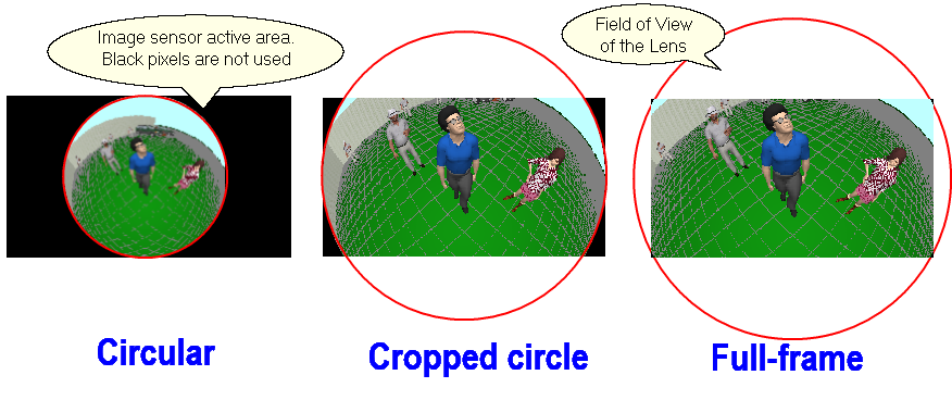
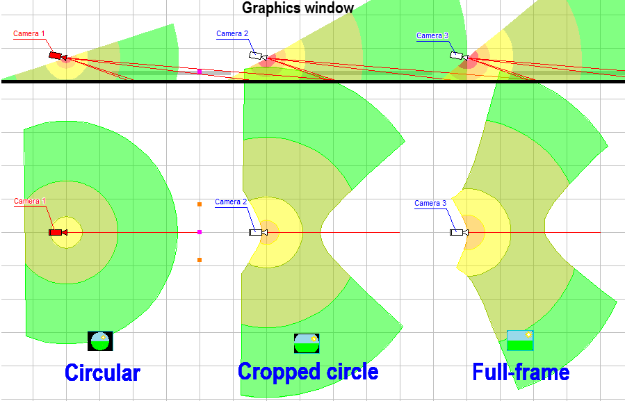
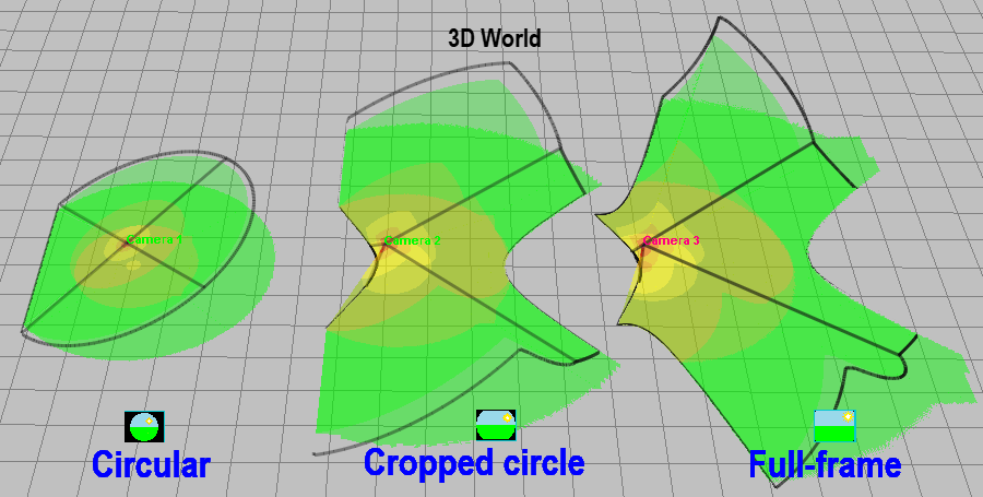
The circular field of view of the FishEye lens can be limited by the image sensor. Depending on this limitation, there are 3 types of FishEye cameras: Circular and limited field of view (Cropped circle and Full frame).
By setting the Sensor limit View angles, any of the three types of Fisheye cameras and their intermediate variants can be simulated.
If you set the type of lens in this field, then the angles of view of the sensor will be calculated automatically. When changing the Aspect ratio, VideoCAD will recalculate the angles to save the selected lens type for the new Aspect ratio.
The viewing angles of Fisheye cameras with a field of view limited by the image sensor (Cropped circle and Full frame) depend on the Mapping function.
The view angles of real lenses may differ from the mathematical model, so if you know the angle values from the camera specification, it is better to enter them directly and not assign the Fisheye type so that VideoCAD models the camera based on real view angles.
For one camera, you can set different view angles for different Aspect ratios / resolutions through the List / Range of lens focal lengths.
See also: List / Range, FishEye
|
The Mapping function determines the distribution of the pixel density of the image sensor between the center and edges of the field of view and depends on the internal construction of the FishEye lens.
Accounting for the Mapping function is not mandatory, it only allows you to increase the accuracy of the modeling Fisheye lenses when necessary. If you do not have information about the type of Mapping function, then set the Equisolid angle function.
See more: Mapping function
|
PTZ camera options. In the PTZ field select Yes if this camera model is PTZ. For a PTZ camera, the maximum angles of rotation horizontally are set, as well as the maximum angles of inclination up and down. The range of the Lens focal lens is set by the List / Range string.
See details: PTZ
|
Multisensor camera parameters.
In the Multisensor field, select Yes if this camera model is multisensor.
Sensors in line - the number of image sensor + lens modules in each line of the multisensor camera. Most cameras have modules in only one line. In this case, it is the number of sensor modules in the camera.
Angle - horizontal angle between sensors in a horizontal line. It is recommended to choose Auto - VideoCAD will calculate the angle itself so that the view areas of neighboring sensors intersect without formation of dead zones.
Order - the order of direction of sensor modules:
Add. lines:
See more: Positions of active camera/Multisensor
|
Optional information about smart features of camera model.
|
Back light compensation control. The parameter determines accessibility of BLC control in the Sensitivity and Resolution box for a camera of this model.
See also: BLC
|
Presence of a build-in microphone.
|
The camera has a Speaker.
|
Presence of a build-in Video Motion Detector.
|
Automatic flip of an image is performed in such a manner that the top of the image always corresponds to the top of view area. Function could be found in AutoDome cameras.
|
Any additional options. |
Supply voltage of camera. |
Power consumption of camera.
|
The consumption current of the camera. The current is calculated by VideoCAD from power consumption and voltage.
On the Used models tab the total current and power consumption of all cameras of this model is displayed additionally.
|
Direct current, Alternating current or Power over Ethernet (PoE). |
Case protection.
If protected housing (waterproof, outdoor or vandalproof) is selected and the Display camera type box is marked (on the Camera and illuminator tab in the Options box), then the icon of the camera of this model in the Icon cell and in the Graphics window will correspond to the camera in housing
Protection can also be set via IP67, IP68, IK10, etc. |
Environment temperature range.
|
Maximum humidity. |
Form of the case.
|
Model sizes.
|
Model weight.
|
Model color. |
CCTV equipment, which is compatible with the model.
|
Software, which is compatible with the model. |
Provider of the camera model.
|
Model cost.
|
Additional costs connected to using the model.
|
The model price including additional costs. Value is calculated by VideoCAD by summing the Cost and additional costs.
On the Used models tab the total cost of all cameras of this model is displayed. |
Any additional information about this camera model.
|
Internet link to an information about this camera model. You can open the link from the pop-up menu of the Camera Table, Table of Camera Models, Camera Model Card window or by clicking on this field.
|