Pixel density |

|

|

|

|

|
||
|
Pixel density |
|
|
|

|

|

|
Pixel density
|
Pixel density |
|
|
|
|
|
||
|
Pixel density |
|
|
|
|
|
|
|
|
||
Graphics window Tool bar
|
|
View area of cameras can be divided into regions based on the following criteria:
|
|
These Criteria relates to the pixel density or the field of view size. For short, in the definitions, it is mentioned the pixel density only (the Pixel density box, the Pixel density pattern, the Pixel density criterion ...), except of special cases.
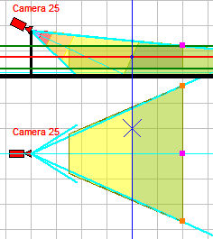
In the Graphics window, projection of different regions of view area can be filled by different color and (or) type of hatching.
Changing the pixel density under the influence of the lens distortion is considered along radial rays from the center of the frame to the edges, without distinguishing between horizontal and vertical.
- contains information about the regions and how they are filled and (or) hatched.
VideoCAD project can contain up to 30 pixel density patterns. Each pattern can include up to 10 regions. You can assign different patterns to different cameras.
Pixel density box
- is designed for creating and editing the patterns of pixel density and field of view size visualization.
In the box there are prepared pixel density patterns according to the following criteria:
| • | Home Office Scientific Development Branch; |
| • | Home Office Guidelines for identification; |
| • | P 78.36.008-99; |
| • | Australian Standard AS4806: Closed Circuit Television; |
| • | European Standard EN 50132-7; |
| • | ISO/IEC 19794 Biometric data interchange formats; |
| • | European Standard EN 62676-4 2015; |
| • | Johnson's criteria for thermal cameras as interpreted by Axis Communications; |
| • | European Standard EN 62676-4 2015 Horizontal. |
Individual patterns can be customized according to any other criteria related to the pixel density or the field of view size.
Also in the box there are examples of images are automatically displayed for each region of pixel density. For the active camera, the distances to the far bounds of regions and the sizes of the field of view at the far bounds of regions are displayed.
Sample images are built automatically based on test images. Several test images are supplied with VideoCAD. You can create test images yourself from your photos using the Edit test image tool.
It is convenient to keep the Pixel density box opened during the analysis of pixel density in the Graphics window. Comparing color of regions on the layout with color in table in the pixel density box, on the images in the Resolution and Field of view columns you can immediately see the expected resolution and field of view size at every point of view area of each camera.
For favorable displaying images on the screen and in the PDF report, the Pixel density box can take the form of tables.
See further : Tools in the Pixel density box, Work with the Pixel density box.
See also: Pixel density, Fill projection, Visualization of cameras' control area projections and pixel density inside them, Calculating pixel density.