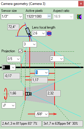
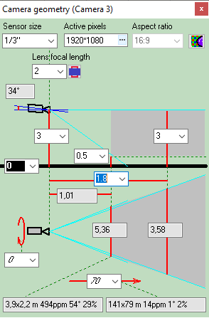
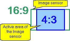
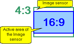
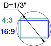
Calculating
size of the active
area of the image sensor in dependence of the aspect ratio
of the image sensor and the aspect ratio of the output image of
the camera.
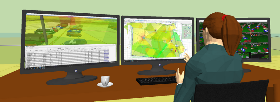
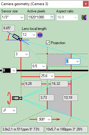
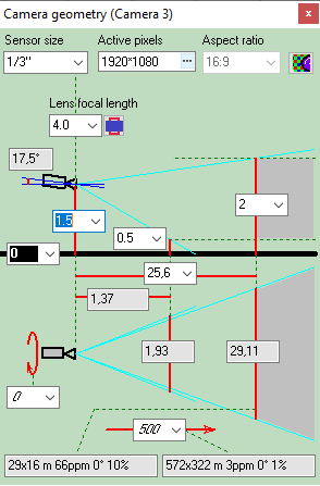
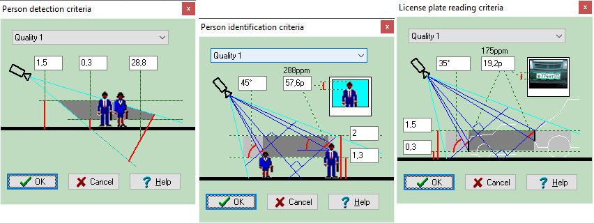
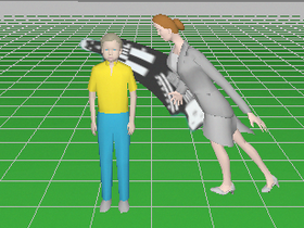
Calculate the horizontal projection sizes of person
detection, identification
and license
plate reading areas.
Calculate the image size on display of any object
in camera view area in percentage of display size, pixels and
millimetres (or inches in case of Imperial format).

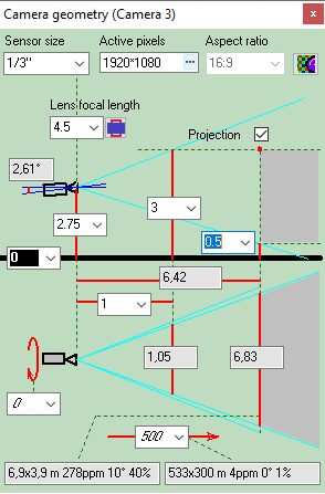
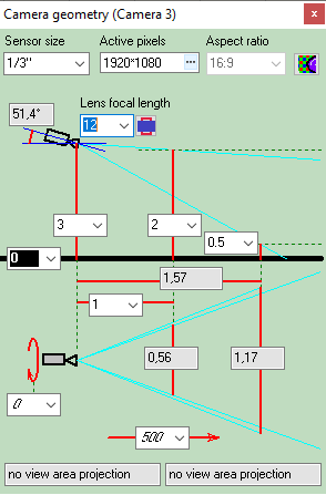
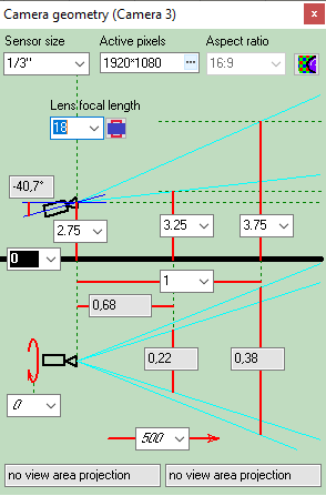
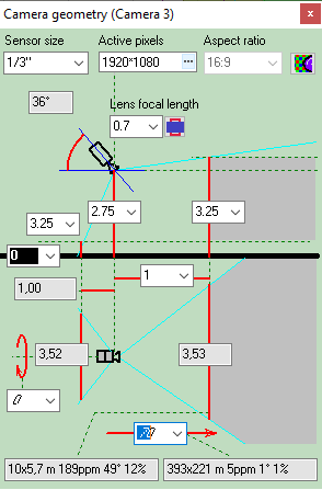
Calculate depth
of field of each camera in project.

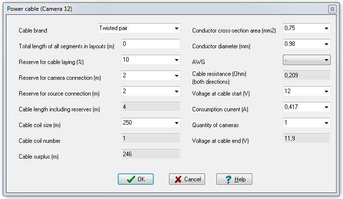
Calculate
the length
and electric parameters of cables.
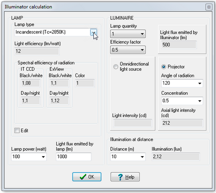
Calculate light power and illumination produced by illuminators
with photometric accuracy, including discharge lamps with complex
spectrum and infrared LED illuminators.
Working with
2D projections
Choose visually a relative location of cameras using the
graphics window with CAD interface. Use a lot of 2D/3D constructions
and CAD tools, snaps,
line types, font types, horizontal and vertical projections, up
to 10 layouts in each project, unlimited number of layers.

2D
modeling in horizontal and vertical projections is possible.
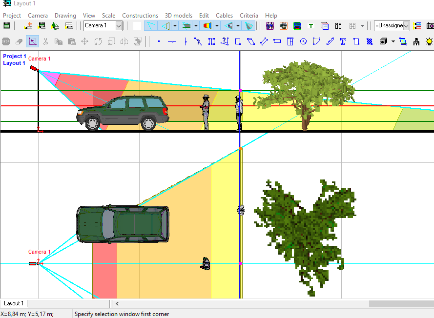
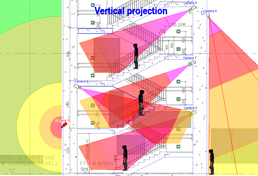
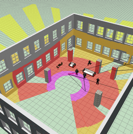
Display on the 2D layout results of calculations:
view area projections, person detection and identification areas,
depth of field limits, test object, cables and luminaries.
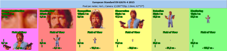
Display by separate colors and hatch styles different regions
of pixel
density and field-of-view size. There are prepared pixel density
patterns according to the following criteria: Home Office Scientific
Development Branch; Home Office Guidelines for identification;
P 78.36.008-99, Australian Standard AS4806: Closed Circuit Television,
European Standard EN50132-7, ISO/IEC 19794 Biometric data interchange
formats, EN 62676-4 2015.


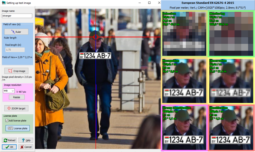
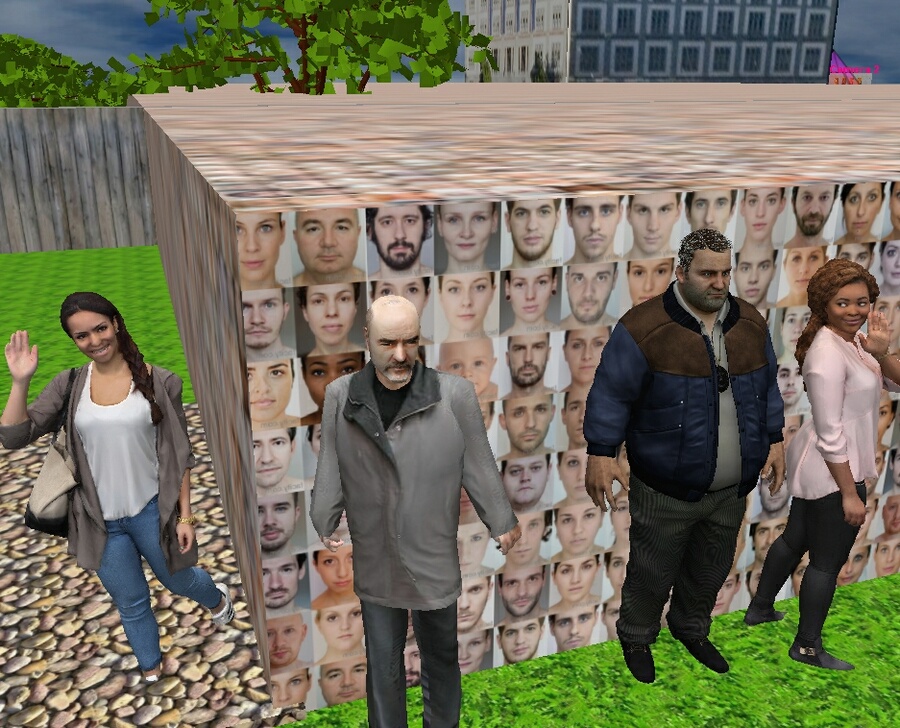
The
Edit Test Image tool to quickly create test images
for pixel density tables from custom photos. Using any photos
allows you to take into account specifics of real goals and scenes.
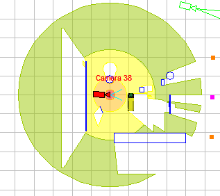
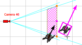
Calculate
the horizontal projection of camera control areas including shadows
from obstacles on the scene.
Choose
the best positions and calculate control areas in
360 degrees.
Modeling
camera
rotation around the main optical axis.

Modeling
lens
distortion. Modeling influence of the lens distortion on view
area shape, on view area projection shape and pixel density distribution.
Correct modeling wide-angle lenses with strong distortion.

Simulating
distortion of varifocal / ZOOM lenses with a complex
dependence of distortion on the focal length.

Quick
assessment of the view of any 3D model through any camera, depending
on relative position of the camera and the 3D model in space.
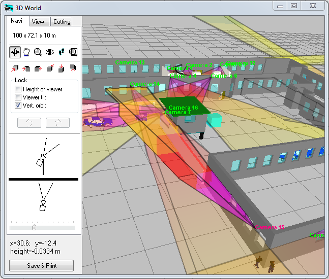
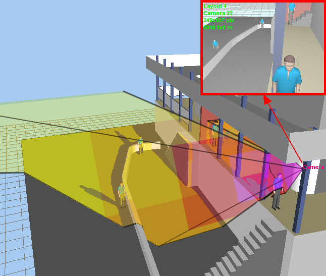
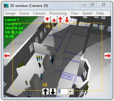
3D
modeling layout and camera view areas
VideoCAD has special 3D
World window with standard tools for 3D
navigation (Orbit, Move, ZOOM, Walk, Look around, Zoom frame).
With the help of the window you can observe the layout in 3D representation.
You can work on the project in usual 2D projections and watch
it in 3D. You can "walk" on the floors of 3D models of buildings
and study every detail.


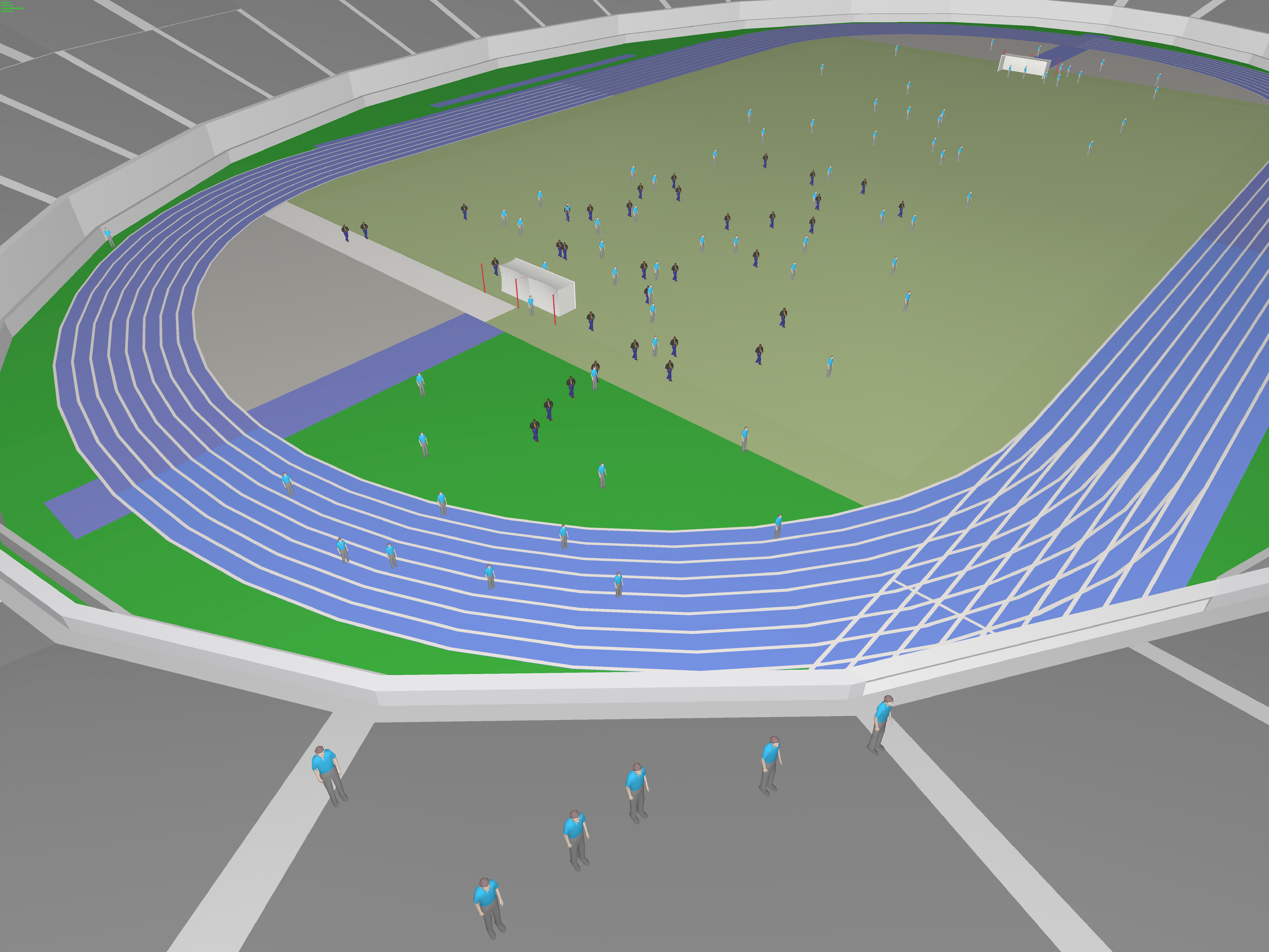
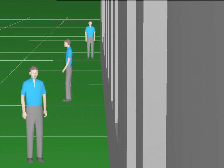
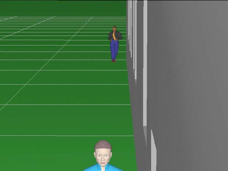
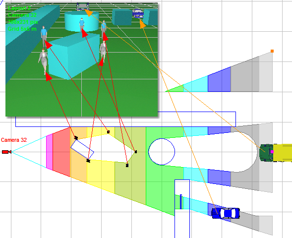
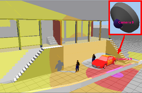
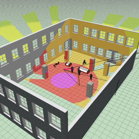
3D
visualization of the
camera view area surface taking into account pixel density,
shadows, lens distortion.

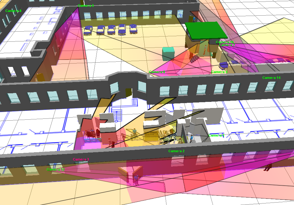
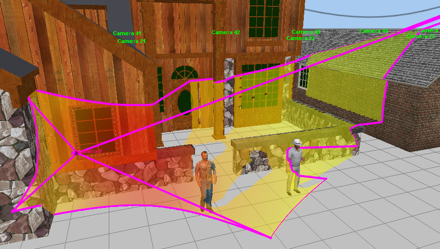
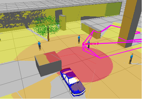
3D
visualization of the active camera
coverage on the environment taking into account pixel density,
shadows, lens distortion.

3D visualization of the control areas of PTZ
cameras, Dome cameras and 360 degree cameras.
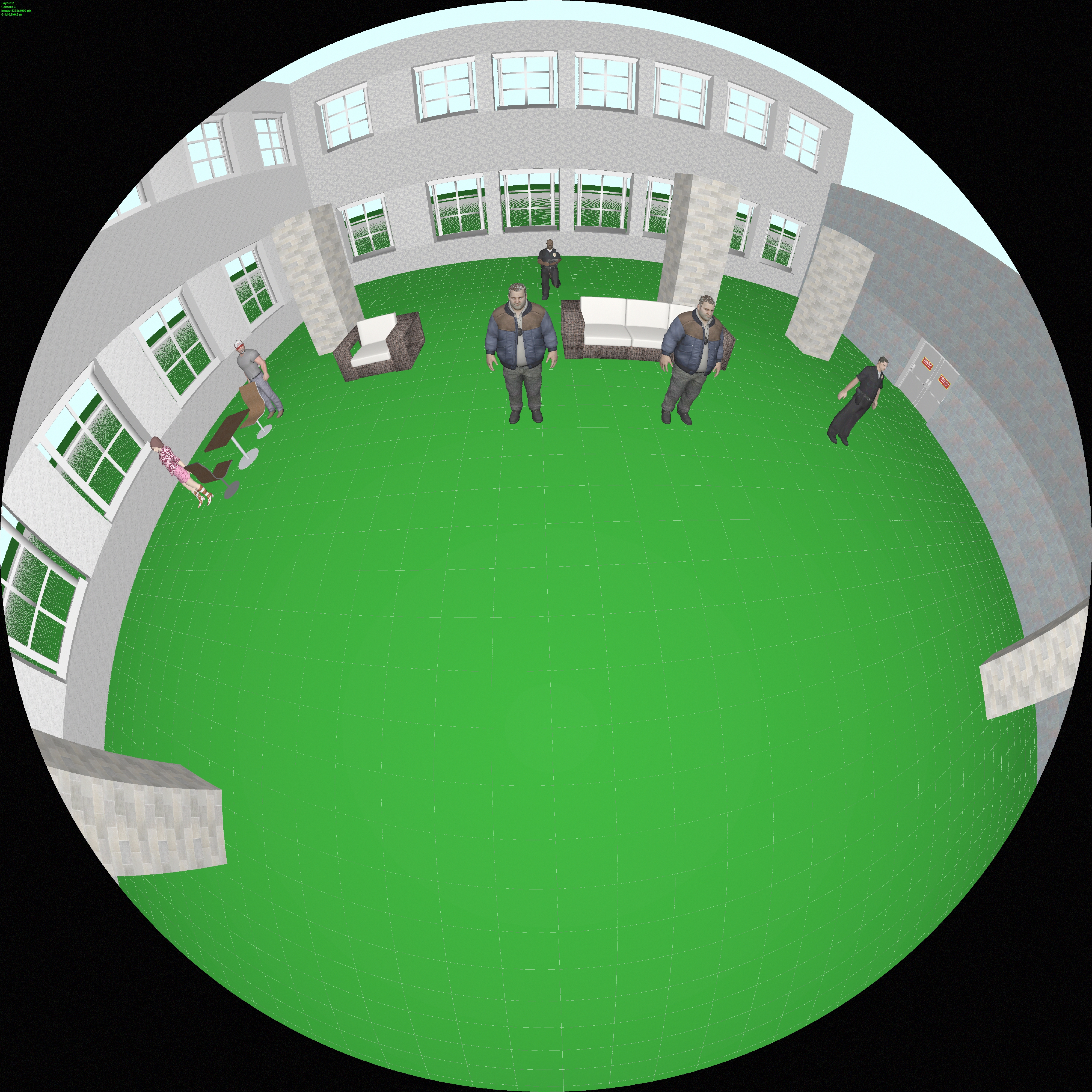
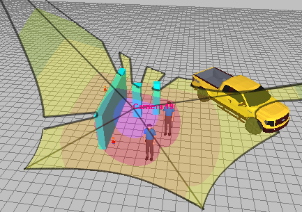
Visualization
of camera coverage area and pixel density distribution on the
surrounding objects of Panoramic
cameras (fisheye, 360°/180°).
Free
cutting
3D layout by six planes to provide access to any point of complex
3D buildings.
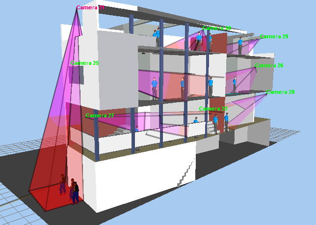
Working
with multilevel
3D layouts and terrains with complicated vertical structure.
Possibility
of loading prepared
3D models (a person, a car, etc.). Built in 3D model library.
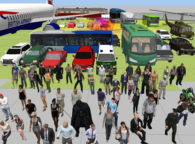
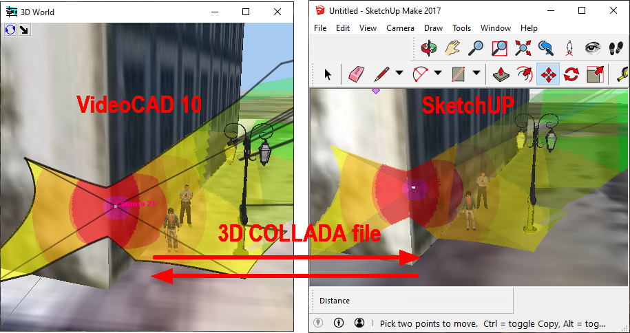
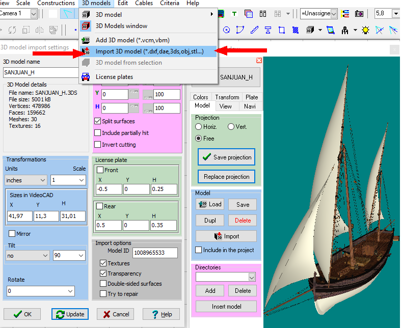
You
can import ready 3D models of objects and territories from
files: *.3ds, *.ase (3D Studio max), *.dae, *.xml (Collada),
*.obj and more than twenty 3D formats. You can download
3D models in Collada format (*.dae) from free SketchUP
3D Warehouse library, use 3DS Max models from designer's libraries,
3D models from game model libraries, create 3D models in SketchUP,
save them in *.dae and import in VideoCAD.
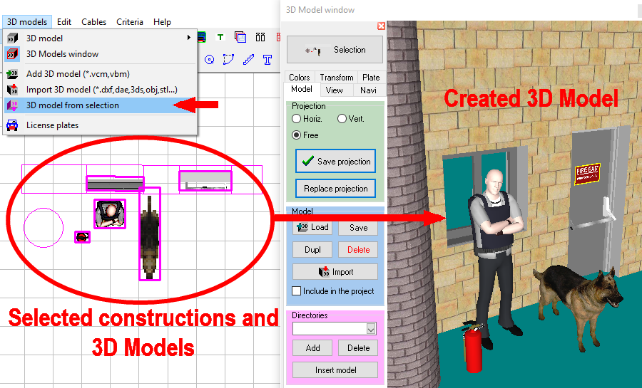
You
can create 3D models in VideoCAD itself from
selected constructions and existing 3D models in any combinations,
you can merge 3D models and constructions.
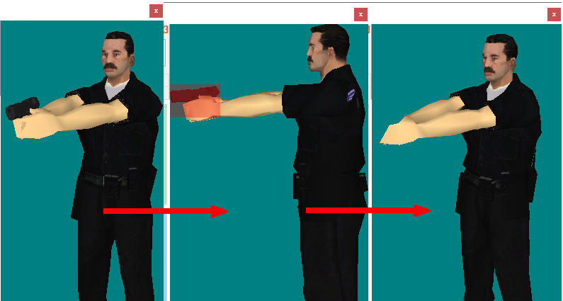
You
can transform, rotate and tilt 3D models (including 3D models
created from constructions).
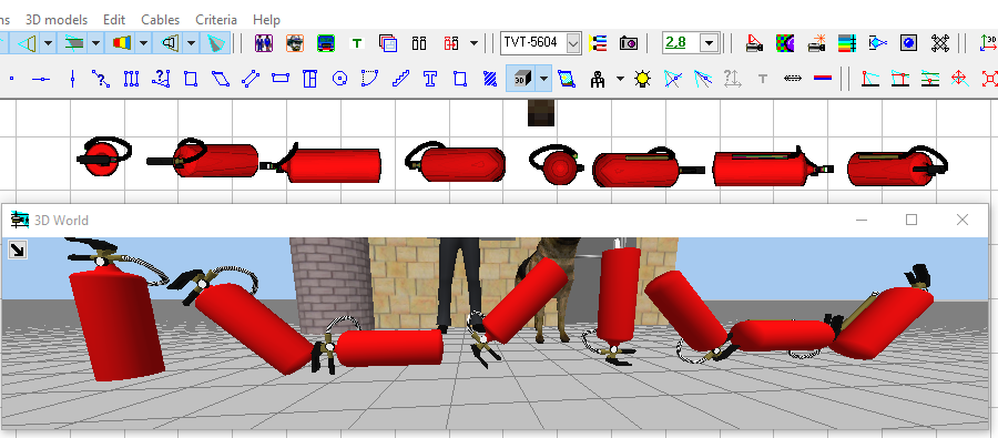
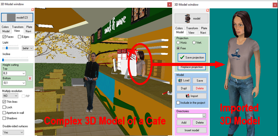
You
can cut out parts from 3D models, import parts from complex 3D
models.
You
can delete parts from 3D models.
You
can import 3D models and scenes from SketchUp using free VideoCAD
Plugin for SketchUP 2.0. The package includes a plug-in, an
example and a User Guide with step-by-step instructions on how
to add a new 3D model to VideoCAD library.
Possibility
of using 3D
models-territories, to place inside them cameras, constructions
and other 3D models.

All
constructions can be not only painted, but also covered by materials.
Any raster images in the formats *.bmp, *.jpg, *.gif, *.tif, *.png
can be used as materials.Using materials you can significantly
improve appearance of images of the project.


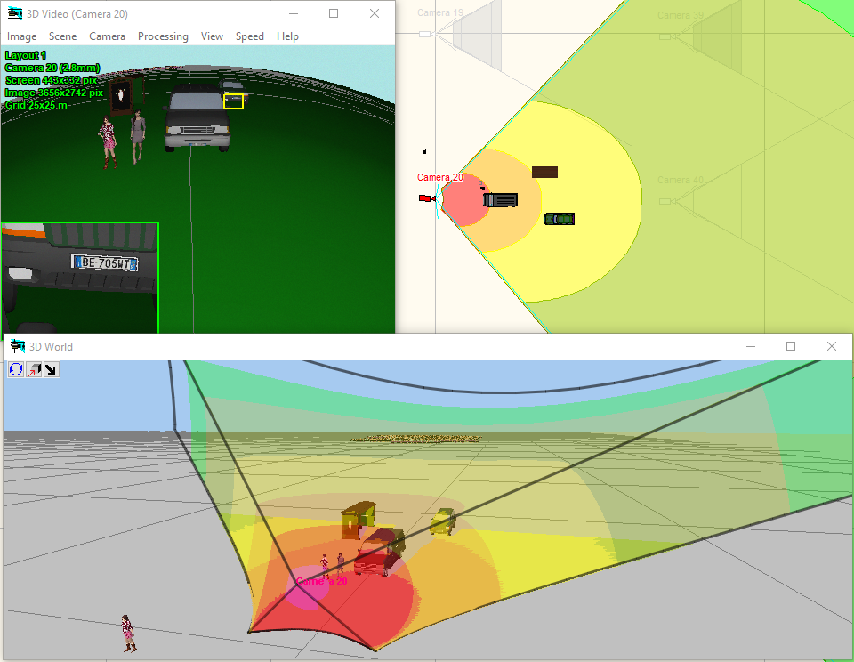
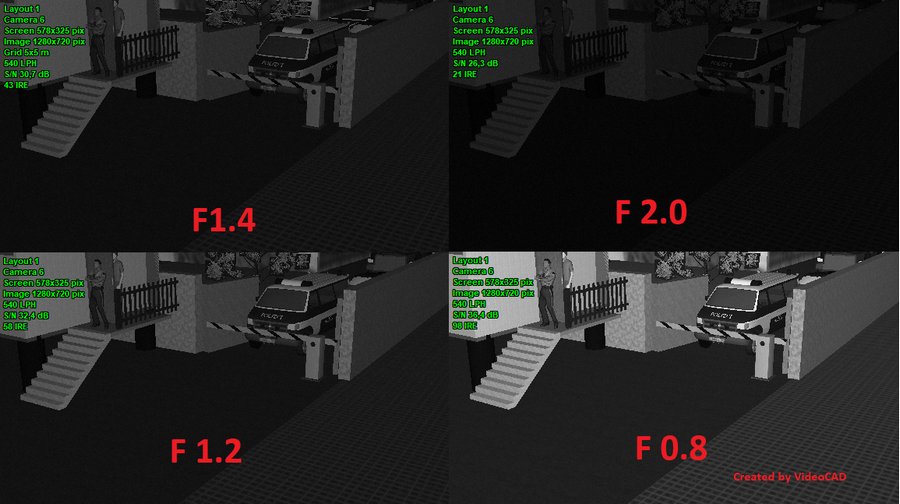
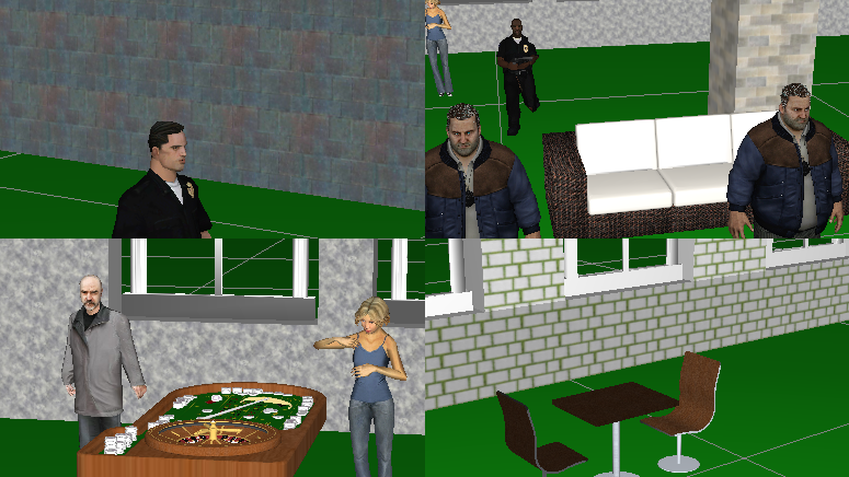
Modeling
images from cameras based on camera parameters and scene conditions
Model observed scene
parameters (illumination, visibility limitations).


Model luminaires
with photometric accuracy considering spectrum of radiation and
spectral sensitivity of image sensors, including discharge lamps
with complex spectrum and infrared LED illuminators.
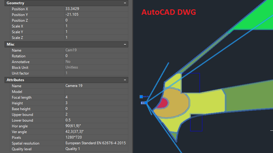
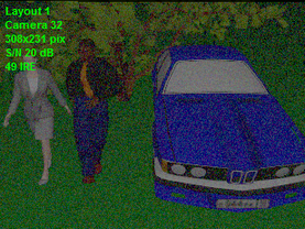
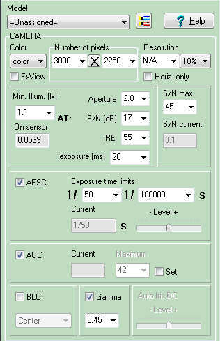
Model camera
parameters (spectral response, number of pixels, resolution,
minimum
illumination at known signal/noise ratio, IRE and aperture,
maximum signal/noise ratio, electronic shutter, AGC, BLC, gamma,
day/night cameras, frame
rate, interlace scan, global shutter and rolling shutter).
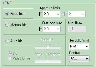
Model
lens
parameters (focal length, aperture, auto iris DC and Video
Drive, resolution).
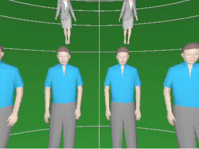
Visually
control modeled resolution with the help of the Test
chart.

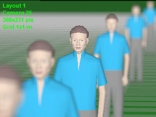
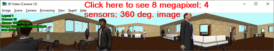
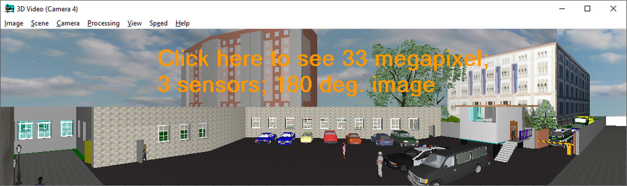
Model
images from megapixel
cameras with number of pixels exceeds Windows screen number
of pixels (Up to 100 megapixel and more!) with PiP
(Picture in Picture) and without PiP.

See
examples: 5
megapixels,10
megapixels, 25
megapixels.

Calculate
and model in 3D depth
of field of each camera in project.
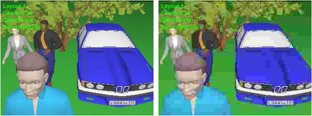
Model brightness,
contrast, compression, horizontal and vertical sharpness.
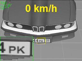
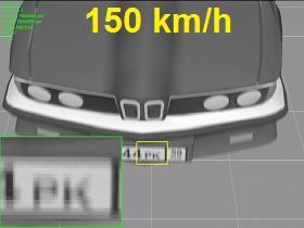
Model moving
objects, camera frame
rate, create animated
images with moving 3D models.
Model blur
and distortion of moving 3D models depending on camera parameters
(exposure time, interlacing, rolling shutter).


Modeling
images taking into account lens
distortion (barrel and pincushion). Correct modeling wide-angle
lenses with strong distortion.

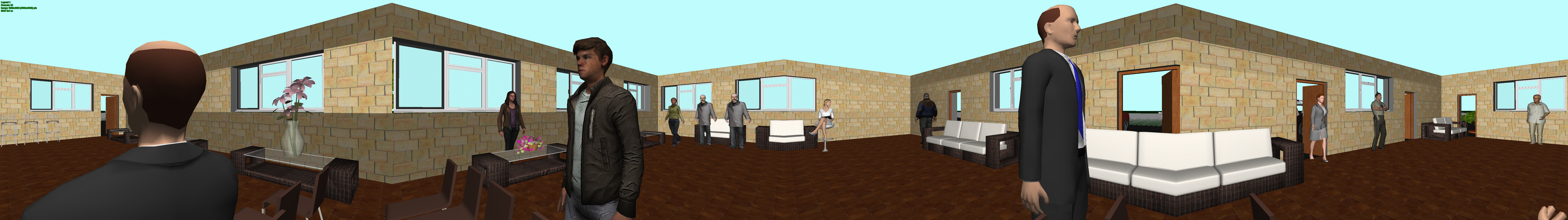
Simulation
of image resolution and view area limits of Panoramic
cameras (fisheye, 360°/180°).

Obtain
Image
Model for each camera in the project based on models of scene
and equipment. This image can be printed and saved.
Modeling
special cameras
Simulation of Day/Night cameras. Setting the
camera sensitivity in color and black-and-white modes. Setting
the moment of switch to the black-and-white mode.
Modeling
horizontal and vertical projections of the view area and visualization
of the pixel density of PTZ
cameras.
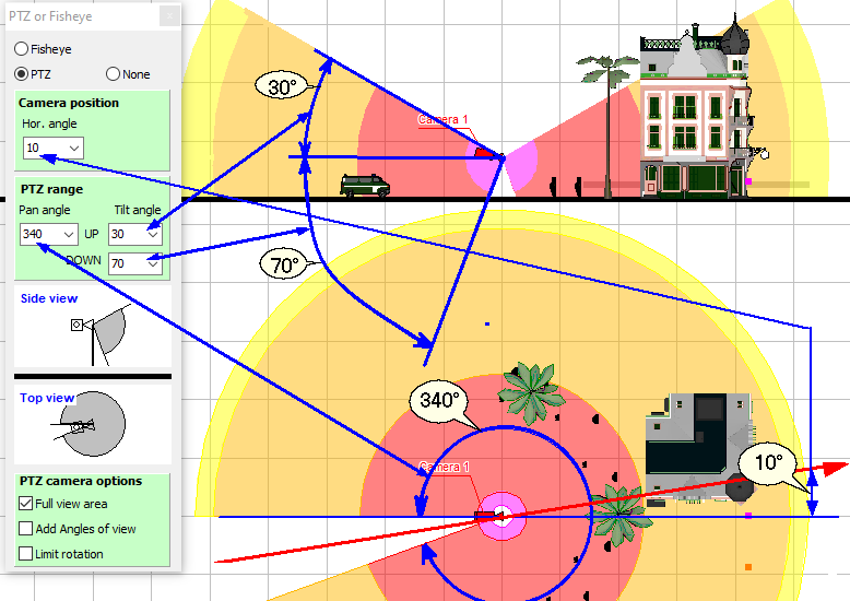
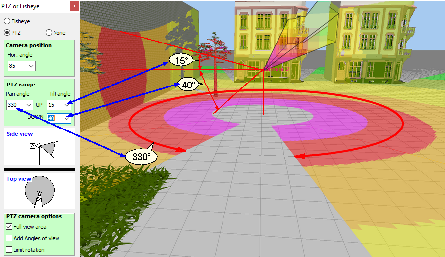
Visualization
in 3D of the coverage area on the surrounding objects and the
pixel density distribution of PTZ
cameras.
Modeling
presets of PTZ
cameras.

Modeling
images from presets of PTZ
cameras.
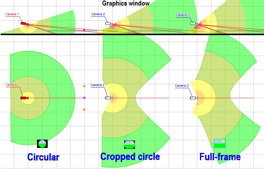
Modeling
horizontal projection of view area and visualization of distribution
of the pixel density of cameras with Fisheye
lens.

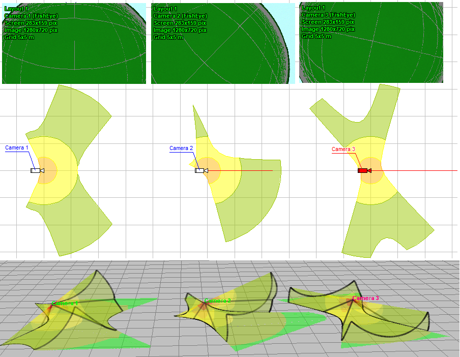
Visualization
of the coverage area on the surrounding objects and the pixel
density distribution of cameras with Fisheye
lens.
Modeling
round images from Fisheye
cameras.

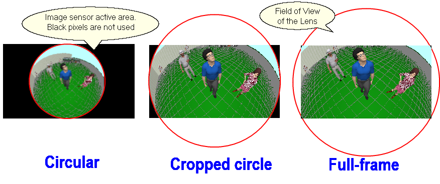
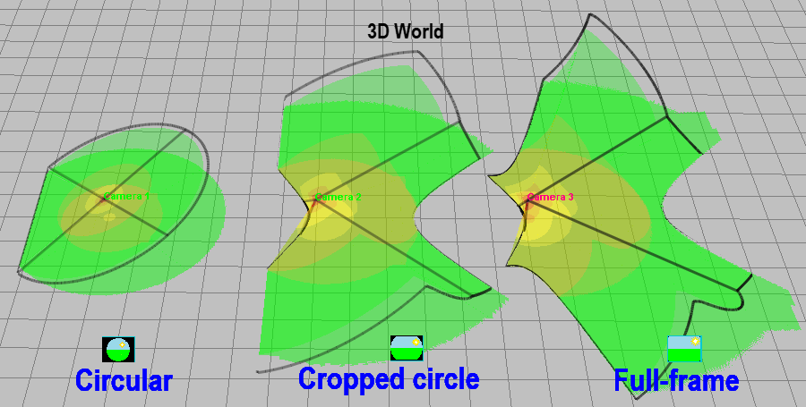
Modeling
combined round images from Fisheye
cameras with one fragment with camera resolution.

Modeling
Fisheye cameras with view area cropped by the image sensor (Cropped
circle and Full frame), as well as any intermediate variants
of the Fisheye view area.
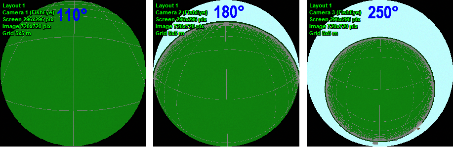
The
ability to change the maximum (circular) view angle of
Fisheye lenses in the range of 110-250 degrees. Thus,
it is possible to simulate both narrow-angle and ultra-wide-angle
Fisheye cameras


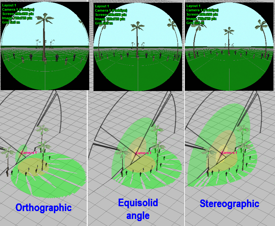
Possibility
of modeling the Mapping function of Fisheye lenses.
The Mapping function determines the distribution of the pixel
density between the center and edges of the field of view and
depends on the internal structure of the lens.
Modeling
dewarped image fragments from Fisheye
cameras with camera resolution.

The
ability to independently set the circular angle of view of the
lens, cropping of the field of view on the size of the image sensor,
the aspect ratio, and the Fisheye mapping function allows you
to simulate a variety of wide-angle cameras with angles up to
250 degrees using the Fisheye parametric model.
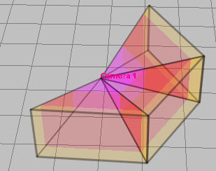
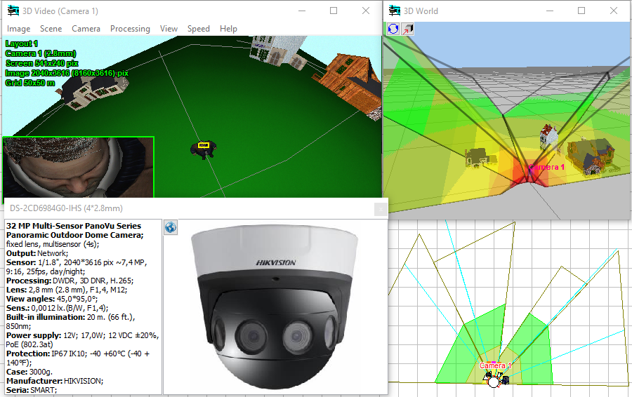
Modeling
horizontal projection of view area and visualization of distribution
of the pixel density of multisensor
cameras with arbitrarily directed modules.

Visualization
of 3D view areas of multisensor
cameras.

Modeling
images from multisensor
cameras with arbitrarily directed modules.

Modeling
multisensor
cameras with horizontal directed modules.

Modeling
multisensor cameras with linked modules and arbitrary
position in space (tilt angle, rotation angle around its axis).
Modeling
matrix multisensor cameras with linked modules
directed in two dimensions and arbitrary position in space.
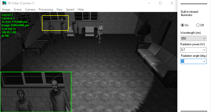
Calculation
and draw on layout the IR illumination zone (where
the built-in IR illumination provides an image of the target with
a quality not worse than the specified one) The calculation is
carried out based on the camera parameters (sensitivity, lens
aperture), IR illumination (wavelength, power, radiation angle,
concentration) and the required target's image quality (signal-to-noise
ratio).

Instead
of a rigorous calculation, you can draw a projection of the IR
illumination zone, setting only the maximum distance of
the IR illumination and the angle of radiation.
Modeling
cameras with built-in
Infrared illuminator.
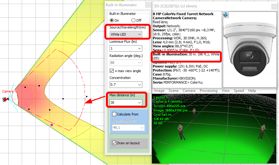
Simulation
of cameras with built-in visible light illumination
and mixed illumination (IR + visible light).
Design
operator interface
Design operator interface using the Monitor
window.
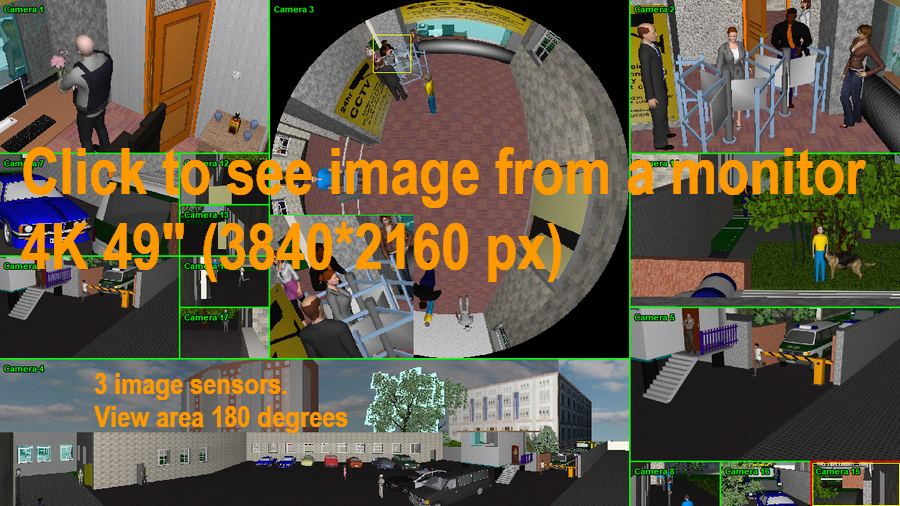
Modeling
resolution
of monitors.
Create
animated
monitor models as html files with moving 3D models and separate
frame rates of each camera.