Measuring rolling shutter row time of IP camera |

|

|

|

|

|
||
|
Measuring rolling shutter row time of IP camera |
|
|
|
|

|

|
Measuring rolling shutter row time of IP camera
|
Measuring rolling shutter row time of IP camera |
|
|
|
|
|
||
|
Measuring rolling shutter row time of IP camera |
|
|
|
|
|
|
|
|
||
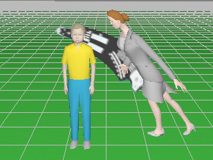
As a result of Rolling Shutter work, exposure of different rows of the image sensor begins and ends sequentially at different times, which causes a horizontal shift of moving objects. This effect occurs with many IP cameras with CMOS image sensor and usually doesn't occur with cameras with CCD image sensor.
|
|
An important parameter of the rolling shutter is the Row time - the difference in time between the beginning exposure of neighboring rows. The less the row time is, the smaller the camera distorts moving objects. Unfortunately this parameter is not given in the camera specification. But it is not difficult to measure the row time in practice.
The row time may vary with different settings of the same camera.
VideoCAD offers a tool for modeling distortions of moving objects depending on the row time. But to use this tool, you need to know the row time.
Problem
There is a IP camera with Rolling shutter. It is necessary to measure its row time - the difference in time between the beginning exposure of neighboring rows.
Equipment:
| • | Oscilloscope. Any analog oscilloscope will suit. |
| • | Low-frequency oscillator. Use any sine wave signal generator of any frequency in the range from 200 Hz to the upper limit of the oscilloscope bandwidth. You can use any homemade generator, software generator for a computer, etc. |
| • | For testing IP cameras it is enough to have possibility to display video on the screen and separate frames. |
| • | A Lens, focal length is 4-8mm. |
| • | Stand. It is recommended for convenience and accuracy. |
Order of work
1. Set the maximum image size in pixels in the camera setting.
2. Set the lens on the camera, install the camera on the stand, point the camera at the screen of the oscilloscope, connect camera to computer, display image from the camera on the computer screen.
The oscilloscope screen must completely cover the field of view in vertical. But it is not necessarily that the oscilloscope screen placed in the frame entirely. It is important that between the oscilloscope screen and the field of view of the camera must not be skew. On the computer screen, lines of the oscilloscope scale should be strictly parallel to the sides of the frame.
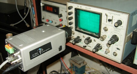
3. Set the oscilloscope sweep time - 50ms/div. Scan - automatic (If your oscilloscope has such settings). Connect the Low-frequency oscillator to the oscilloscope.
On the oscilloscope screen a flying thin vertical line must be visible. On the computer screen instead of the thin vertical line, thick inclined line will be seen. The thickness of the line in the scale of oscilloscope screen equals to the camera's exposure time. The inclination of the line is determined by the row time of camera's rolling shutter.
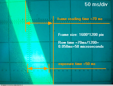
4. Save and view a frame in which the inclined line gets wholly. If you can not get such frame, increase the oscilloscope sweep to 100ms/div. If inclination is not enough, decrease the oscilloscope sweep to 20ms/div.
5. To calculate the row time, first read a difference between the edge of the line on the top and on the bottom of the frame in the scale of the oscilloscope screen - frame reading time = 70ms. And then divide the resulting time by the number of rows in the image (1200) and get the row time = 58 microseconds.
6. Repeat measurements for other frame sizes of the same camera.
In the tested by us IP camera the frame reading time wasn't changed when changing the frame size from 640*480 to 1600*1200, and was about 70ms. Thus, the row time was from 58 to 146 microseconds depending on the number of rows in the frame.
Perhaps the opposite situation, when the row time is stable, but the frame reading time depends on the number of rows in the frame.
See also: Image parameter panel>Camera>Rolling shutter
External link: "The principles of CCTV design in VideoCAD. Part 5. Video surveillance of moving objects"(*.pdf)