

Options Miscellaneous |

|

|

|

|

|
||
|
Options Miscellaneous |
|
|
|

|

|

|
Options
Miscellaneous
|
|
||
Graphics window Main menu View Options Miscellaneous |
|
Calculate shadow for active camera
Enable/ disable calculating shadows.
Automatic calculating is performed for the active camera only.
To disable automatic calculating shadows (with keeping already calculated shadows) clear this box.
This box is duplicated in the Main menu of the Graphics window.
This checkbox has an influence on calculation of shadows in the Graphics window only, it hasn't influence on the 3D World.
See also:Shadows,Main menu>View>Calculate shadows for active camera, Main Menu>View>Recalculate shadows,Line type>Shadow, Layers>Shadow, Options box>Miscellaneous>Shadow, Options box>Calculate shadows from 3D models, Current construction parameter panel>3D model>Shadows, 3D Models window>Shadows, Choosing the best place for PTZ (dome) camera, Visualization of the camera control area projections and pixel density within them
Calculate shadow from 3D models
The calculation of shading from complex 3D models in the Graphics window - resource-intensive operation.
The calculation is disabled by default to save resources. To enable the calculation of shading from 3D models, mark the Calculate shadows for 3D models box.
Additionally, for each 3D model, which must be taken into account when calculating the shading:
| • | double click on the model to switch it to editing state; |
| • | on the appeared Current construction parameter panel check Shadow checkbox. |
In addition,
| • | line type of the instance of 3D model must have Shadow checked; |
| • | the 3D must belong to a layer with Shadows field checked; |
This checkbox has an influence on calculation of shadows in the Graphics window only, it hasn't influence on the 3D World. Calculation of shadows from 3D models in the 3D World requires much less computer power. It is convenient to use this checkbox to disable shadow calculation from 3D models in the Graphics window only, where this calculation requires a lot of resources, but leave the calculation of shadows from 3D models in the 3D World.
3D models with marked the Shadows checkbox in the 3D models window are considered as obstacles in the calculation of shading regardless of state of this checkbox Calculate shadow from 3D models.
See also:Shadows,Main menu>View>Calculate shadows for active camera, Main Menu>View>Recalculate shadows,Line type>Shadow, Layers>Shadow, Options box>Miscellaneous>Shadow, Options box>Calculate shadows from 3D models, Current construction parameter panel>3D model>Shadows, 3D Models window>Shadows, Choosing the best place for PTZ (dome) camera, Visualization of the camera control area projections and pixel density within them
Calculate shadow for active camera once
As a result of clicking this button, shadows for active camera will be calculated once, then the Calculate shadow for active camera box will be cleared and shadows will not be calculated anymore. Shadows have been calculated will be saved in project.
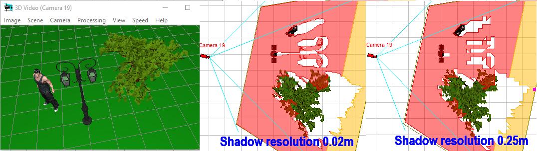
In the combobox you can set a compromise between the speed and accuracy of the calculation of shadows. The smaller the number in the box, there are more accurately calculated shadows, but the more time is required to the calculate.
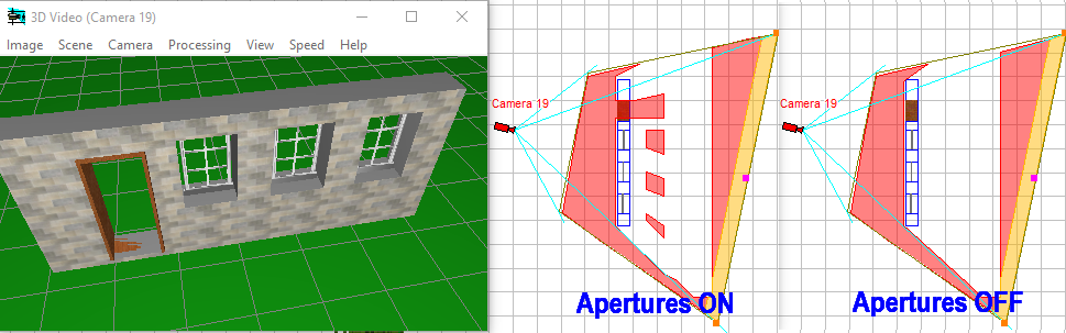
Take into account apertures in ![]() walls (made by the
walls (made by the ![]() Aperture in wall tool or by the 3D models of windows or doors) while calculating shadows.
Aperture in wall tool or by the 3D models of windows or doors) while calculating shadows.
Shadow calculator optimization
In the combobox, you can select optimal settings for calculating shadows according to features of the project:
| • | universal settings; |
| • | settings optimized for calculating shadows from a large number of spaced obstacles; |
| • | settings optimized for calculating shadows from 3D models. |
With this panel, you can adjust auto saving VideoCAD's working projects to chain of files in intervals specified in the Interval (min). The number of files is specified in the Depth box . The more files in the chain are and the larger the file size of the project, the more hard disk space will require. After full filling the chain, saving each new file will remove the oldest. You can specify autosave directory by clicking on the Dir button.
Files in the chain are the usual project files of VideoCAD. The newest file called vcadproject_1.vc7, previous vcadproject_2.vc7 etc.
Auto saving works while working with the program. When no work, saving stops.
On the panel you can enable printing via buffer that allows to print without error on printers which do not support GDI+ drawing commands of transparent fills, gradient and transparent projection of 3D models. Via the buffer you can print without errors on most virtual printers, such as printing to PDF.
When using the buffer printing on the raster buffer is performed firstly, and then the raster buffer is passed to the printer.
Without the use of the buffer the image is passed to the printer in vector form, as printing commands. If the printer does not support all commands, the distortions of the printed image are possible.
However not all printers can work with the Use buffer mode in all cases. In case of issues clear the Use buffer checkbox. Try also to decrease printer DPI resolution, hide raster background.
When using the print buffer or if the printer does not scale hatching, to print hatching properly check the option Scale hatching. If the printer scales hatching on their own and the buffer is not used, clear the Scale hatching, otherwise the hatching will be printed too rare.
Thin lines of raster background
Mark of this checkbox increases the thickness of the thin dark lines on a light background to one pixel when displaying raster background in the Graphics window. In most cases it improves readability of the background when it is scaled.
This mode decreases speed of redrawing background.
Correction factor to bring the physical size of the Monitor window on the computer screen to the value specified in the Monitor diagonal box on the Tool bar of the Monitor window.
To set the factor:
| • | open the Monitor window; |
| • | specify in the Monitor diagonal box on the Tool bar of the Monitor window approximately a half of the physical diagonal of your computer screen. The Monitor window must be visible on the screen as a whole; |
| • | measure by a ruler the physical diagonal of the Monitor window on the computer screen; |
| • | calculate the needed Monitor size factor = (value in the Monitor diagonal box) / (Physical diagonal of the Monitor window). |
The Monitor diagonal is measured in inches. 1 inch = 25.4 mm.
For various physical monitors and screen settings in Windows may require different Monitor size factors.
In the combo box, you can select the lens distortion modeling method for cameras with distortion modeling enabled. The selection in this box affects all cameras with distortion modeling at the same time.
| • | Do not simulate - do not simulate lens distortion. The cameras will use view angles calculated from the lens focal length and size of active area of the Image sensor; |
| • | Simulate Accurately - Accurately simulate lens distortion. In case of inaccurate initial data, the picture may be distorted. Displaying dozens of cameras with distortion on the screen at the same time can lead to delays. |
| • | Simulate Simplistically - just assign vertical and horizontal actual view angles to the model, regardless of the lens focal length and the size of the active area of the image sensor. An undistorted picture will be obtained regardless of the accuracy of the angle values. The accuracy of the simulation depends on the accuracy of the angles, but in any case it is worse than with the exact simulation of lens distortion. Simplified distortion modeling requires much less resources to redraw the screen in 2D and 3D. |
| • | Auto select - choose the method of modeling lens distortion automatically depending on the input data. |
See more: Lens distortion,
Critical focal length for Auto select
If Autoselect is selected in the Lens distortion combo box, the lens distortion modeling method is automatically selected. One of the selection criteria is the value of the Lens focal length. If the Focal length is greater than the critical one, then the distortion is modeled in a simplified way, since it is believed that the distortion of long-focus lenses is small and can be neglected.
See also: Lens distortion,
Modeling the lens distortion in VideoCAD is performed with limited sampling, which can be changed in this box. Than more the value in the box is, the more segments will be used in calculation of distortion, the more precision, less artifacts, but the longer it takes for redrawing images with distortion.
See also: Lens distortion,
Under the influence of lens distortion, the image becomes non-linear, stretched or compressed along the distance from the center of the frame to its edges. As a result, rectangular regions in scene space are no longer rectangular on the image sensor, and square pixels of the image sensor are no longer square in scene space. This leads to ambiguity in the definition of pixel density.
If this checkbox is checked, then when modeling distortion, the pixel density will be considered as the number of pixels per unit area in the frame. If the checkbox is not checked, then the pixel density will be calculated along the distance from the center to the edge of the frame.
In practice, the effect of this checkbox is small, it can be left checked by default. This checkbox can be useful for particularly precise modeling.
Base heights of cameras in vertical projection
If the checkbox is checked, then when cameras are placed in the vertical projection, of the Graphics window their heights above the ground will be equal to the sum of the camera installation height, the base height of the camera and the height in the parameters of the group to which this camera belongs.
If the checkbox is not checked, then in the vertical projection the camera height is set equal to only the Camera Installation Height. Camera Base Height and Camera Group Height are not taken into account.
