Visualization of cameras' control area projections and pixel density inside them
Feedback on: VideoCAD - Visualization of cameras' control area projections and pixel density inside themPRIM22_SpatialResExamples of work with VideoCAD > Visualization of cameras' control area projections and pixel density inside them /Dear CCTVCAD Software,
Visualization of cameras' control area projections and pixel density inside them
We have a three-dimensional model of a complex environment.
We need to determine the areas controlled by cameras taking into account shadows arising from obstacles of the environment (camera control areas). Within the control areas, the pixel density of cameras must be visualized.
We should be able to estimate directly on the 2D site plan how people will look into the camera image at each point of the camera control area.
Order of work
1. Construct three-dimensional model of the environment using the tools of 3D modeling.
The constructions must be drawn by line types with marked Shadow box.
You can import the environment or its fragments in the form of one or several 3D models imported from other graphics formats.
If the environment contains 3D models, shadows from which must be taken into account, you must:
6. Choose Within projection in the drop-down menu of the Shadowbutton on the Tool bar.
After a while VideoCAD calculates the control area projection, taking into account shadowing from obstacles in environment.
Click to expand
7. Keep the Pixel density box opened.
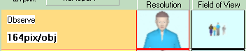
It is convenient to keep the Pixel density box opened during the analysis of pixel density in the Graphics window. Comparing color of regions on the layout with colors in the Table of regions in the Pixel density box, on the images in the Resolution and Field of view columns you can immediately see the expected resolution and field of view size at every point of view area of each camera.