Measuring camera sensitivity |

|

|

|

|

|
||
|
Measuring camera sensitivity |
|
|
|
|

|

|
Measuring camera sensitivity
|
Measuring camera sensitivity |
|
|
|
|
|
||
|
Measuring camera sensitivity |
|
|
|
|
|
|
|
|
||
See before:About camera sensitivity.
Problem
There is a camera. It is necessary to measure its sensitivity.
The matter of measurement of sensitivity is a measurement of scene illumination with which the camera image have Signal/Noise ratio = 17dB. To measure illumination a Luxmeter is used, to measure Signal/Noise ratio the Image analyzer or the Video analyzer from the CCTVCAD Lab Toolkit package can be used.
The Video analyzer reads out the Signal/noise ratio directly from the screen.
The Image analyzer uses the stored frames in *.bmp or *.jpg formats.
In most cases the Video analyzer is more convenient for measuring signal/noise ratio.
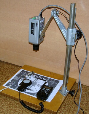
Equipment:
To perform the measurements you need the software CCTVCAD Lab Toolkit (visit http://cctvcad.com ).
If the lower limit of illumination measured by the luxmeter is more than assumed camera sensitivity, see Measuring low illumination.
For measuring IP cameras' sensitivity it is enough to have possibility to display images on the screen and save images.
IP cameras sensitivity can worsen considerably depending on compression level.
If the camera allows to mount only mini-lenses (M12), the mini-lens with a known aperture (F2.0) is needed.
Measuring sensitivity should be carried out in a dark room.
|
|
Order of work
1. Switch off all additional options of image processing. Only AESC and AGC should be switched on. Switch maximal gain of AGC if it is possible.
For IP cameras, set the compression type - M-JPEG, the image quality - the best. While measuring the sensitivity of IP cameras you must know which exposure time is used by the testing camera, otherwise the measurement becomes meaningless.
See Measuring exposure time of IP camera.
Sensitivity of IP cameras can depend on the number of pixels in image. The higher the number of pixels is, the smaller pixel size - the worse the sensitivity.
Correctly measuring sensitivity of modern IP cameras is not an easy task. When light is decreased, IP camera automatically turns on the noise reduction, merges neighboring pixels, reduces frame rate, multiplies exposure time, disables color. The black level rises and the noise is lost in black together with dark image details. Meanwhile turning off this automation is impossible in many cases.
2. Mount lens F1.2, on the camera, mount the camera on stand, direct it towards the test chart, connect to computer, display image on the screen.
If the camera allows mounting only mini-lenses (M12), mount a mini-lens with known aperture (F2.0).
3. Direct on the test chart, in the camera field-of-view place the luxmeter sensor.
4. Defocus.the image slightly to blur possible unevenness on the chart.
5. Switch on tungsten halogen lamp. Switch off common light.
6. Changing the distance from the lamp to the test chart, get an image with visible noises on the screen.
You must not change the lamp supply voltage. It should be equal to nominal lamp supply voltage. Change Illumination only be means of distance variation between the lamp and the test chart.
Be sure, that the luxmeter sensor window and the grey scale of the test chart have visually equal illumination.
7. Save the image and record illumination according to the luxmeter reading.
If luxmeter sensitivity is not enough, see Measuring low illumination.
8. Repeat p.6.. 7 for different illumination.
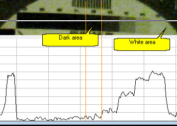
9. Measure signal/noise ratio for saved images by means of the Image analyzer. As a white area use the white area of paper near to the luxmeter sensor window. As a dark area use one of rectangle of the grey scale.
About choice of the dark area in details: The dark area must meet two requirements: 1. Noise at the area should be not be greatly restricted by the black level. 2. It should be exactly the darkest area.
With standard analog cameras it is usually enough to choose the black darkest square on the gray scale. Automation analog camera works in such a way that the black level is kept when changing the light, not cutting off the signal and noise. Complicated analog cameras with digital processing, IP cameras can behave unpredictably. Sometimes while changing light levels some of squares in the gray scale goes for the black level or rise above the black level, black level "floats." In this case we have to choose to measure different areas, making sure that the dark area is really darkest and the noise is not cut by the black level.
|
|
10. Find image with signal/noise ratio equal 17dB. Record Maximum level of brightness and illumination at which this image is obtained.
11. Value of illumination at which the image is obtained is the Minimum scene illumination for the tested camera at signal/noise ratio equal 17dB and lens F1.2 (F2.0 for a camera with mini-lens).
The Maximum level of brightness is the IRE at the minimum illumination.
You can insert these values into the Table of camera models or in the Sensitivity and Resolution box. After that it is possible to perform precise modeling of the tested camera model.
3
With complicated analog cameras and IP cameras may be a situation when we can not get the signal to noise ratio equal to 17dB because of constantly working noise reduction schemes. If the noise reduction can not be disabled, then we can not use the Signal/Noise ratio as a boundary criterion of sensitivity. In this case we have to choose another boundary criteria, for example the image resolution. Precise modeling of the sensitivity of these cameras is not possible, but an approximate simulation of images details may be sufficient for practice.
See also: About camera sensitivity, Measuring low illumination, Sensitivity and Resolution>Camera, Table of camera models.
External link: "The principles of CCTV design in VideoCAD. Part 4. Illumination and camera sensitivity in CCTV"(*.pdf) .