3D Video Main menu |

|

|

|

|

|
||
|
3D Video Main menu |
|
|
|

|

|

|
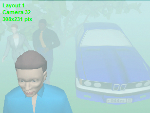
3D Video
Main menu
|
|
||
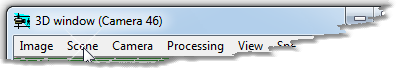
In the Main menu there are commands of image saving and printing and a part of image parameter adjustments, which duplicate adjustments on the Image parameter panel for faster access. All image parameters are presented on the Image parameter panel. The panel can be called by right or double clicking on the image in the 3D Video.
The menu is divided into groups according to the order of image processing from the camera:
| • | Image - saving and printing current image in the 3D Video; |
| • | Scene - parameters of the scene; |
| • | Camera - parameters of the camera; |
| • | Processing - processing the obtained image, by the camera and other CCTV equipment; |
| • | View - visibility of auxiliary objects on the image model; |
| • | Speed - fast switching between redrawing speed and exactness of modeling 3D images. |
Image Save as *.bmp ( *.jpg, *.gif, *.tif, *.png)
Scene According to camera parameters
Camera |
Processing According to camera parameters
View According to camera parameters
Speed Redraw 3D image only by clicking
|
If this item is checked , the frame from the 3D Video will be saved or printed with its real size in pixels , regardless of the size of the 3D Video window .
The frame size is specified in the Sensitivity and Resolution box and in the Image parameter panel > Processing tab.
This tool as well as the PiP tool, allows modeling megapixel images .
When modeling distortion is enabled and the Real frame size is checked, the obtained images will have real resolution of distortion. Another way to get the real resolution with lens distortion - see PiP.
Generation of frames with size more than the 3D Video window size or generation of frames with distortion requires additional time and computer resources. Depending on the capabilities of your video card and computer may be some problems with large size images , especially when modeling large images with distortion . If errors occur , try to disable distortion or decrease the frame size
The Real frame size.item doesn't affect to animated images.
You can save full-size images from all or selected cameras to a specified directory during generation of the PDF report.
|
Image > Save as *.bmp ( *.jpg, *.gif, *.tif, *.png)
Save the static image in the 3D Video in any format from the following: *.bmp, *.jpg, *.gif, *.tif, *.png. These items are inaccessible , when the image is animated, the Animate box is checked and Number of frames is more than one.
See also: Real frame size.
|
Image > Save as animated *.gif
Animation works only in VideoCAD Professional
Save the animated image in the 3D Video in the animated *.gif format. This item is inaccessible , when the image is not animated, the Animate box is not checked or Number of frames equals one.
The Real frame size.item doesn't affect to animated images.
|
Copy the image to Windows clipboard. After that the image can be pasted into other program.
|
Choosing this item opens a standard dialog box of current printer setup in Windows.
|
Print image in the 3D Video.
See also: Real frame size, Drawing>Print
|
Scene > According to camera parameters
Different cameras can be in various conditions and consequently for different cameras scene parameters can be different. If this item is checked, scene parameters are set according to scene parameters of active camera. As a result of activation of other camera, scene parameters will be changed according to scene parameters of this camera. Manual changing scene parameters is disabled.
If this item is not checked, scene parameters could be specified manually. The set parameters will not be changed during activation of different cameras.
See also: Image parameter panel>Scene, Save
|
Sensitivity of cameras is modeled only in VideoCAD Professional
During the day, scene of the same camera can be essentially changed. In daytime there is predominance of the natural illumination, and at night artificial one. In daytime the sky is much brighter than the ground, and at night it is darker (because of the predominance of artificial illumination). Therefore for each camera 2 sets of scene parameters are specified: for day and night time. If this item is checked, scene parameters of day time is used, otherwise scene parameters of night time is used.
The effect of this item is applied to all cameras at once. Actually it is a switch of time in the project. The same switch is available in the Monitor window.
See also: Image parameter panel>Scene
|
The item opens a submenu, in which the Lamp position relative to the active camera can be chosen.
Background light source produces background scene illumination. Except the background light source on a scene it is possible to place illuminators.
See also: Image parameter panel>Scene
|
Sensitivity of cameras is modeled only in VideoCAD Professional
If this item is checked, during 3D image generation, scene illumination parameters, illuminators and camera sensitivity are considered.
Image generation time can considerably increase.
If the item is not checked, illumination is not considered, only camera view area is modeled.
Illumination modeling can be switched on separately for each camera, for day time or night time.
See also: Image parameter panel>Scene
|
Sensitivity of cameras is modeled only in VideoCAD Professional
If this item is checked, during 3D image generation, switched on illuminators, placed on the scene, are considered. If the item is not checked, the illuminators are not considered.
The item is accessible only if illumination modeling is switched on.
Illuminators can be switched on separately for each camera, for a day time or night time.
See also: Image parameter panel>Scene, Illuminator
|
Scene > Meteorological Visibility
Meteorological Visibility is the greatest distance at which it is just possible to see with the unaided eye:
This parameter is reported in a weather forecast, and can be also visually determined.
Rough values of Meteorological Visibility for various weather conditions according to data of meteorologists:
Pay attention to the following moments:
Meteorological Visibility does not coincide with the maximal person detection range. Meteorological Visibility is calculated in respect of black big size object against background of fog or sky. Maximal person detection range, limited by visibility, is 1.5-2 times less at the average depending on contrast between background and person's clothes.
At surveillance in the night time and at illumination from the camera the maximal detection range is considerably reduced due to light reflection from fog (rain or snow).
At modeling the threshold of eye contrast sensitivity 0.03 is accepted.
Quality of visibility range modeling has a great dependence from video card's opportunities and its adjustments. Modern 3D-accelerator allows getting excellent quality of modeling. At the same time without the accelerator, accurate modeling fog is insufficient.
See also: Errors in rendering 3D images
|
Show the Scene tab on the Image parameter panel. On the tab all scene parameters are presented. In the main menu there is only a part of the parameters.
See more: Image parameter panel>Scene
|
Show the Table of camera models. In the table it is possible to set parameters to models and assign any model to the active camera.
See more: Table of camera models
|
The Item opens submenu, which makes possible switch on unitary or permanent depth-of-field modeling. Initial data (lens focal length, aperture and focus distance) are set in Depth-of-field box. Clicking the Parameters item it is possible to display this box.
More detail about Depth-of-field see General information about Depth of field in CCTV.
Modeling Depth-of-field takes much time (depending on complexity of scene, video card's and computer's opportunities (from several seconds to one minute), therefore it is not recommended to mark needlessly the item Model permanently, otherwise the program will work very slowly.
Quality of modeling considerably depends on video card's opportunities and its adjustments. If depth of field modeling does not work or works incorrectly, try to change adjustments of video card hardware acceleration. If in your video card there is no hardware support of this function, Depth of field should be modeled at completely switched off hardware acceleration (the slider is moved to the left). However in this case quality of other parameters of image is worsened.
See also: Errors in rendering 3D images
|
The Item opens submenu, which makes possible switch on unitary or permanent exposure time modeling. This item duplicates corresponding panel on the Camera tab on the Image parameter panel.
Modeling Exposure time takes much time (depending on complexity of scene, video card's and computer's opportunities (from several seconds to several minutes), therefore it is not recommended to mark needlessly the item Model perm., otherwise the program will work very slowly.
Quality of modeling considerably depends on video card's opportunities and its adjustments. If modeling exposure does not work or works incorrectly, try to change adjustments of video card hardware acceleration. If in your video card there is no hardware support of this function, exposure should be modeled at completely switched off hardware acceleration (the slider is moved to the left). However in this case quality of other parameters of image is worsened.
See also: Errors in rendering 3D images
|
Show the Camera tab on the Image parameter panel. On the tab the active camera parameters are presented. In the main menu there is only a part of the parameters.
See more: Image parameter panel>Camera
|
Camera > Sensitivity and Resolution
Show the Sensitivity and Resolution box in which there are parameters of sensitivity and resolution of the active camera.
Sensitivity parameters take part in modeling only if 3D Video is opened and illumination modeling is switched on.
See more. Sensitivity and Resolution
|
Processing > According to camera parameters
Images from different cameras can be processing by various means and consequently for different cameras the processing parameters can be different. If this item is checked, processing parameters are set according to processing parameters of the active camera. As a result of activation of other camera, processing parameters will be changed according to processing parameters of this camera. Manual changing processing parameters will be disabled.
If this item is not checked, processing parameters could be specified manually. The set parameters will not be changed during activation of different cameras.
See also: Image parameter panel>Processing
|
If this item is checked, the vertical resolution of the image sensor is reduced in half. Vertical resolution decreases, if video signal from a camera with interlace scan is captured by fields (half frames), instead of full frames. For example, 768x288 pixels.
|
The item opens a submenu, in which the image brightness can be chosen.
|
The item opens a submenu, in which the image contrast can be chosen.
|
The item opens a submenu, in which the image compression level can be chosen.
Compression levels may differ from the compression levels in the settings of different DVR or IP cameras. To determine a correspondence use the visual image comparison.
Obtained image compress by the JPEG algorithm for approximating the image in the 3D Video to the real image from video cameras to exactly estimation the possibilities of detection, identification and reading
Using in your DVR algorithms different from JPEG is not generally an obstacle for compression modeling with the help of JPEG algorithm. Although other algorithm artifacts differ from JPEG artifacts, the general amount of information correspondence that can be determined by the careful visual image comparison is enough for modeling.
|
Show the Processing tab on the Image parameter panel. On the tab the image processing parameters are presented. In the main menu there is only a part of the parameters.
See more: Image parameter panel>Processing
|
View > According to camera parameters
You can set visibility of additional elements separately for different cameras. If this item is checked, visibility of additional elements are set according to parameters of active camera. As a result of activation of other camera, visibility of additional elements will be changed according to parameters of this camera. Manual changing visibility of additional elements will be disabled.
If this item is not checked, the visibility could be specified manually. The set visibility will not be changed during activation of different cameras.
See also: Image parameter panel>View
|
Place the following information in the left upper corner of the image:
For Fisheye cameras the Image line displays a virtual number of pixels for correct simulation of resolution of Fisheye camera. The simulated resolution is exact only at the center of the frame. Towards the edges of the frame the actual resolution is worse than simulated. The smaller the view angle, the more accuracy of simulating resolution on the edges of the frame.
|
With this item, you can quickly turn on and off the PiP (Picture in Picture) mode. The PiP mode is designed to simulate an image with a resolution exceeding size in the 3D Video window.
See more: PiP
|
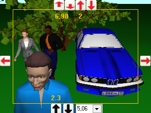
PTZH frame (Pan-Tilt-Zoom-Height) allows operating camera similarly to PTZ one and additionally change camera's installation height.
Above the frame the buttons, which changes view area upper bound distance
It is recommended to set view area upper bound height, which is equal to maximal height of observed objects, and do not change it further. Further adjust camera's inclination by changing only the view area upper bound distance.
On the right and to the left of the frame there are camera rotation buttons
Under the frame there are buttons, which change the height of camera installation
Using these tools it is possible to rotate the camera in both planes, change lens focal length and height of installation.
To change the position on one step click corresponding button. For continuous moving bring the cursor to the button, then press it and do not release the left mouse button. For precise position adjustment do the same, but with pressed Ctrl.
In the PTZH frame mode you can pan and tilt the camera by moving the image like moving drawing in the Graphics window. Press left mouse button, move cursor with the button pressed then release the mouse button. Camera tilt angle is changed through changing view area upper bound distance. But when Ctrl is pressed, the tilt angle is changed through changing view area upper bound height. You can pan camera using arrow keys.
Frame PTZH disables image processing, titles and animation.
Together with Monitor window this tool offers a new method of 3D CCTV design.
If a model is assigned to the camera, and the model has fixed focal length lens, then you can not change the focal length.
If a model is assigned to the camera, and the model has a lens with limited variable focal length, then you can change focal length within the limits only. When approach to the limit values, the box will become crimson.
You can change focal length in wide range of 0.5-1000mm of cameras, which have not assigned model or the assigned model have not specified limits of the lens focal length.
Changing the lens focal length and therefore the calculated values of view angles of camera with enabled modeling lens distortion will lead to detuning parameters of distortion and warping view area form. To correct the mismatch you should set new values of the actual view angles, taking into account the changed values of calculated view angles.
The PTZH frame simulates lens distortion in simplified way. Only border of the field of view is drawn without modeling optical distortion of the image.
|
See more: Background, Background resolution
|
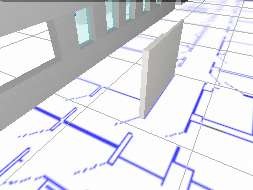
Show or hide ground surface. Ground color can be set on the 3D modeling tab on the Options box.
In multi-level 3D projects the height of the ground surface equals to the base height of the active camera.
|
|
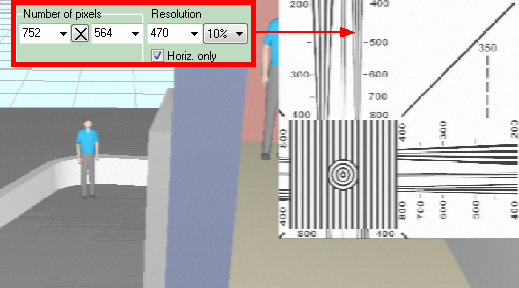
Place at the right top corner the image fragment of the standard test chart EIA1956 for the visual estimation of the current horizontal and vertical resolution. The Test chart shows resolution in lines per picture height (LPH) regardless of the Aspect Ratio.
Result of measuring resolution by this fragment of EIA1956 test chart equals to the modern ISO 12223. Use of EIA1956 is caused that it is more compact.
Maximum resolution what can be measured by the middle field without multiplication is 1600 LPH. With the help of combo box under the Test chart checkbox on the View tab of the Image parameter panel, you can increase the size of the chart in 2 or 4 times or reduce the size in 2,4,8,16,32,64 times, and thus expand the range of measured resolution to 50-102400 LPH.
You can simulate the image resolution using the tools Camera>Resolution (LPH), Lens>Resol.(lp/mm), Processing>Sharpness, Depth of Field.
You can get images with the number of pixels exceeds the screen size using the tools Real frame size and PiP.
You can measure contrast drop using the TV - lines tool from the CCTVCAD Lab Toolkit package.
See also: 3D Video window, , Real frame size
|
Show the View tab on the Image parameter panel. On the tab you can show or hide all additional elements on the 3D image. In the main menu there is only a part of the elements.
See more: Image parameter panel>View
|
Speed > Disable image processing
This item duplicates the same box on the 3D modeling tab on the Options box.
If this box is marked then the image processing will not be modeled. Modeling gamma, noise, brightness, contrast, resolution, sharpness, compression, titles, animation, exposure time and depth of field will be disabled.
Redraw speed will increase, errors with outdated video cards may be removed.
Image processing is disabled by default. When you try to activate features that require image processing, a message is displayed.
|
Speed > Redraw 3D image only by clicking
This item duplicates the same box on the 3D modeling tab on the Options box.
Modeling complex 3D scenes, especially taking into account illumination, require high computer performance. If the image in the 3D Video is redrawn too slowly and that hinder operation in the Graphics window, mark this box. After that the image in the 3D Video will be redrawn automatically only at activation of cameras. To force redrawing click on the image. |
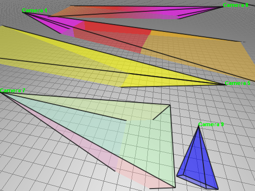
If this item is not checked, then for acceleration only objects that get into the camera's view area no further than the Maximum distance of drawing view area are drawn. As a result, some of objects may be missing on the image. If this item is checked, then all objects on the current layout are drawn. This can increase redrawing time.
|
Open the Help system topic with the information about 3D Video. |