About lens distortion |

|

|

|

|

|
||
|
About lens distortion |
|
|
|

|

|

|
About lens distortion
|
About lens distortion |
|
|
|
|
|
||
|
About lens distortion |
|
|
|
|
|
|
|
|
||
Studying the manufacturers specifications of lenses and cameras we can see that in many cases the actual view angles obtained by measurement and listed in the specification do not coincide with the calculated view angles for an ideal lens, based on the lens focal length and the size of the image sensor.
For example, the specification of the lens T2314FICS-3 (Computar) contains the following values:

With lens focal length of 2.3 mm and the size of the image sensor 1/3" real horizontal view angle is 113.30 deg., and the vertical view angle is 86.30 deg. But calculation gives lower values - 92.40 deg. and 76.10 deg.
The form of the camera view area with this lens differs from the standard pyramid and therefore can not be accurately calculated by lens calculators or modeled by CCTV design programs of previous generation.
The cause of warping the view area is the Lens distortion. The Lens distortion arises from the fact that the optical magnification of a real lens is not constant over the entire field of view. Optical magnification varies depending on the distance from the center to the edges of the field of view.
Depending on whether the optical magnification of a lens is decreased or increased with distance from the center of the field of view, the barrel distortion and the pincushion distortion is distinguished.
The titles barrel and pincushion are associated with the distortion of the image. But the shape of the field of view varies oppositely the title. Thus, with the barrel distortion the image resembles a barrel, and the shape of the field of view resembles a pillow. With the pincushion distortion, the image resembles a pillow, and the shape of the field of view - a barrel.
Lens distortion leads to warping:
| • | shape of view area and field of view; |
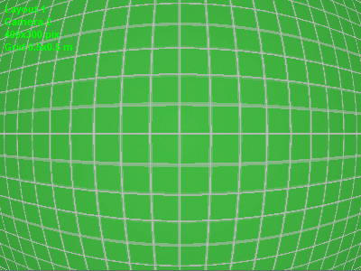
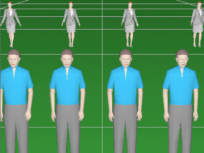
| • | image from the camera; |
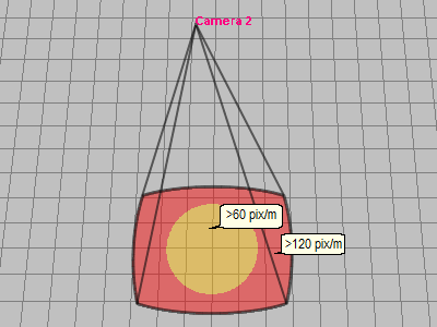
| • | distribution of the pixel density. |
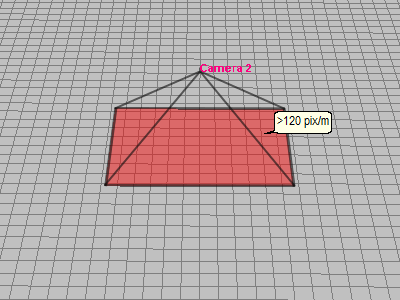
The Lens distortion should not be confused with the Perspective distortion (Fig. 7), which is natural on all images obtained with wide-angle lenses. Perspective distortion does not change pyramidal shape of the view area, rectangular shape of field of view and distribution of the pixel density.
If by moving away from the center of the field of view the optical magnification decreases, then objects at the edges of the field of view seem compressed, and the pixel density decreases from the center to the edges, and the field of view is stretched to the edges. Real angles in this case are more than the calculated angles. This is called Barrel distortion. The Barrel distortion is most common and usual for wide angle lenses.
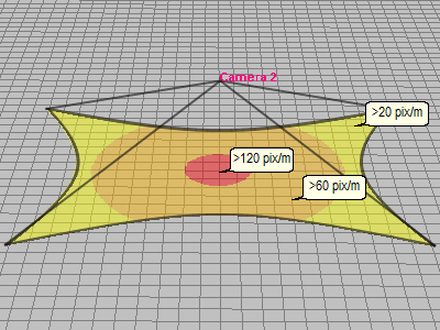
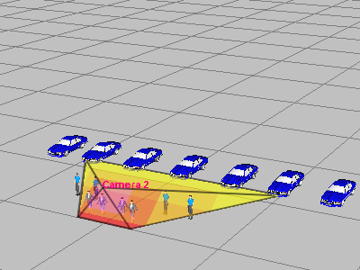
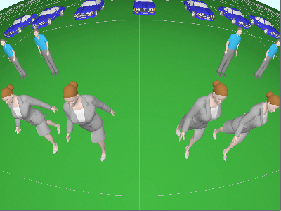
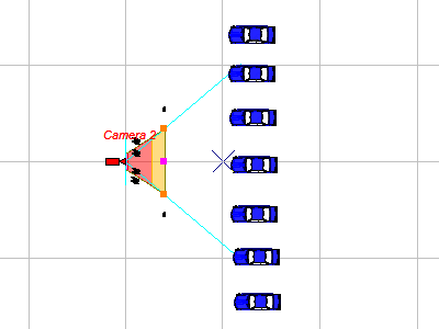
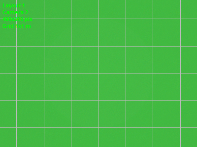
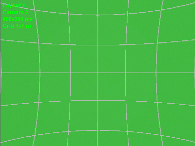
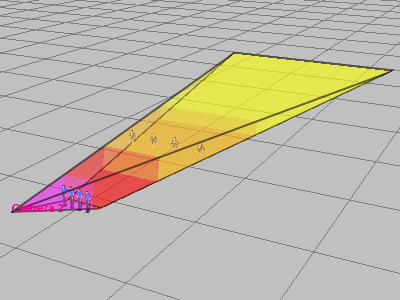
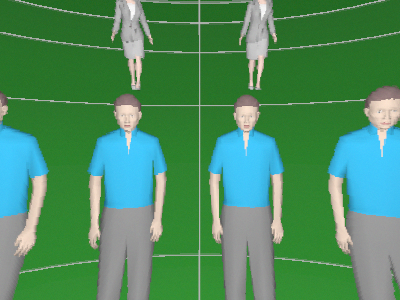
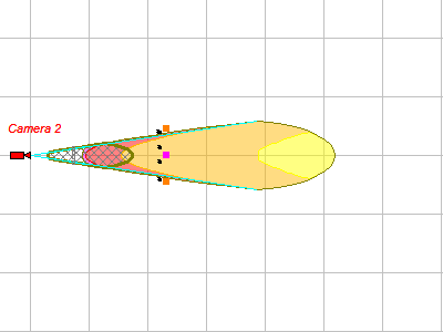
In particular, the lens T2314FICS-3 has just the Barrel distortion. Let's consider a model of image from this lens, the model of field of view, view area projections built with and without simulating distortion. Position of the camera in both cases is constant.
Note the warping of distribution of the pixel density (Fig. 4). Barrel distortion increases the field of view, but reduces the pixel density, the farther from the center of the field of view, the stronger.
|
||||||||||||||||||||||||||||||
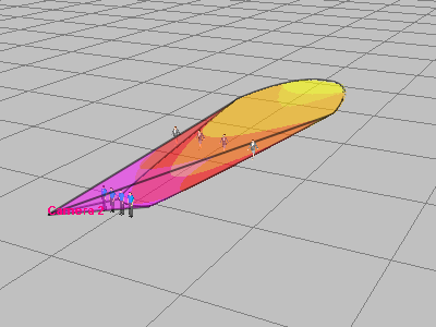
If by moving away from the center of the field of view the optical magnification increases, then objects at the edges of the field of view seem stretched, and the pixel density increases from the center to the edges, and the field of view is compressed to the edges. Real angles in this case are less than the calculated angles. This is called Pincushion distortion. The Pincushion distortion occurs seldom with teleobjective lenses.
Let's consider models built with and without simulating distortion. The models are given to illustrate the pincushion distortion, they are not associated with a certain model of lens. Position of the camera in both cases is constant.
Note the warping of distribution of the pixel density (Fig.14). Pincushion distortion decreases the field of view, but increases the pixel density, the farther from the center of the field of view, the stronger.
|
||||||||||||||||||||||||||||||
![]() Modeling lens distortion in VideoCAD
Modeling lens distortion in VideoCAD
Camera specifications do not contain a "lens distortion" parameter, therefore VideoCAD simulates distortion based on real view angles, which, as a rule, are given in the specifications.
The easiest way is to simulate lens distortion of cameras whose specification contains at least two real view angles (horizontal and vertical). To simulate distortion, it is enough to enter into VideoCAD values of two real view angles and the image resolution in pixels (from the image resolution, VideoCAD will calculate the Aspect ratio).
It is somewhat more difficult to model the lens distortion of cameras, the specification of which contains only one real view angle (horizontal). To simulate the distortion, in addition to the value of one real angle, the exact sizes of the active area of the image sensor are required. The sizes of the active area of the image sensor can be determined by other parameters available in the specification, however, this may be difficult for an inexperienced user.
See: Specifying active area size of the image sensor.
If the camera specification does not contain any real view angles, then the Lens distortion can be simulated only approximately using the real view angles of similar cameras with the same lens focal length and the size of the active area of the image sensor. It is possible to measure real view angles practically.
If you set real angle values too differed from calculated angles or set other inconsistency, then the boxed will colored in Red and (or) the view area will be corrupted.
|
See more: Lens distortion, Modeling lens distortion, Measuring real view angles List/Range
See also: Specifying active area size of the image sensor