Image parameter panel View |

|

|

|

|

|
||
|
Image parameter panel View |
|
|
|

|

|

|
Image parameter panel
View
|
Image parameter panel View |
|
|
|
|
|
||
|
Image parameter panel View |
|
|
|
|
|
|
|
|
||
On the tab the image size in the 3D Video and visibility of additional elements on the 3D image are specified.
Some elements on this panel are duplicated in the Main menu of 3D Video.
See also: 3D Video
According to camera parameters
|
|
According to camera parameters
You can set visibility of additional elements separately for each camera. If this box is checked, visibility of additional elements are set according to parameters of active camera. As a result of activation of other camera, visibility of additional elements will be changed according to parameters of this camera. Manual changing visibility of additional elements will be disabled.
If this box is not checked, the visibility could be specified manually. The set visibility will not be changed during activation of different cameras.
The box is duplicated in the Main menu of the 3D Video.
See also: Save to camera
|
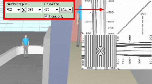
In the box horizontal image size in the 3D Video is specified. Near this box, the calculated vertical image size and the Aspect Ratio is shown.
If the According to camera parameters box is marked, Size on the screen (pix) is taken from camera parameters. But only if for this camera the Image size on the Processing tab is not specified. If the Image size is specified, the Size on the screen (pix) becomes equal to the specified Image size.
The Image size in the 3D Video can not exceed screen resolution. How to model high resolution images, see Real image size and the PiP tab.
See also: According to camera parameters
|
Animation works only in VideoCAD Professional
Time of animated image generation increases in proportion to the number of frames.
The frame rate can be specified in the corresponding box on the Camera tab.
On the animated image the 3D models with non-zero speed will move, the Rotakin will rotate.
Animated images can be saved in the animated gif files , and also can be displayed on the Monitor and saved in html file.
To make visible movement on an animated image, in the view area 3D models with non-zero speed and (or) object Rotakin must present.
See also: Creating animated model of monitor. External link: "The principles of CCTV design in VideoCAD. Part 5. Video surveillance of moving objects"(*.pdf)
|
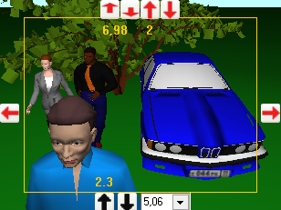
Place the following information in the left upper corner of the image:
For panoramic cameras the Image line displays a virtual number of pixels for correct simulation of resolution of panoramic camera.
|
PTZH frame (Pan-Tilt-Zoom-Height) allows operating camera similarly to PTZ one and additionally change camera's installation height.
Above the frame the buttons, which changes view area upper bound distance
It is recommended to set view area upper bound height, which is equal to maximal height of observed objects, and do not change it further. Further adjust camera's inclination by changing only the view area upper bound distance.
On the right and to the left of the frame there are camera rotation buttons
Under the frame there are buttons, which change the height of camera installation
Using these tools it is possible to rotate the camera in both planes, change lens focal length and height of installation.
To change the position on one step click corresponding button. For continuous moving bring the cursor to the button, then press it and do not release the left mouse button. For precise position adjustment do the same, but with pressed Ctrl.
In the PTZH frame mode you can pan and tilt the camera by moving the image like moving drawing in the Graphics window. Press left mouse button, move cursor with the button pressed then release the mouse button. Camera tilt angle is changed through changing view area upper bound distance. But when Ctrl is pressed, the tilt angle is changed through changing view area upper bound height. You can also pan camera using the arrow keys.
Frame PTZH disables image processing, titles and animation.
Together with Monitor window this tool offers a new method of 3D CCTV design.
If a model is assigned to the camera, and the model has fixed focal length lens, then you can not change the focal length.
If a model is assigned to the camera, and the model has a lens with limited variable focal length, then you can change focal length within the limits only. When approach to the limit values, the box will become crimson.
You can change focal length in wide range of 0.5-1000mm of cameras, which have not assigned model or the assigned model have not specified limits of the lens focal length.
Changing the lens focal length and therefore the calculated values of view angles of camera with enabled modeling lens distortion will lead to detuning parameters of distortion and warping view area form. To correct the mismatch you should set new values of the actual view angles, taking into account the changed values of calculated view angles.
The PTZH frame simulates lens distortion in simplified way. Only border of the field of view is drawn without modeling optical distortion of the image.
See also: CCTV design using Monitor window and PTZH frame
|
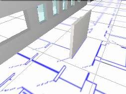
See more: Background, Background resolution
|
Place at the right top corner the image fragment of the standard test chart EIA1956 for the visual estimation of the current horizontal and vertical resolution.
The Test chart shows resolution in lines per picture height (LPH) regardless of the Aspect Ratio.
Result of measuring resolution by this fragment of EIA1956 test chart equals to the modern ISO 12223. Use of EIA1956 is caused that it is more compact.
Maximum resolution what can be measured by the middle field without multiplication is 1600 LPH. With the help of combo box under the Test chart checkbox on the View tab of the Image parameter panel, you can increase the size of the chart in 2 or 4 times or reduce the size in 2,4,8,16,32,64 times, and thus expand the range of measured resolution to 50-102400 LPH.
You can simulate the image resolution using the tools Camera>Resolution (LPH), Lens>Resol.(lp/mm), Processing>Sharpness, Depth of Field.
You can get images with the number of pixels exceeds the screen size using the tools Real frame size and PiP.
You can measure contrast drop using the TV - lines tool from the CCTVCAD Lab Toolkit package.
See also: 3D Video window, , Real frame size
|
|
Show/Hide the Grid.
|
|
|
Show/Hide 3D the ground surface. Ground color can be set on the 3D modeling tab in Options box.
In multi-level 3D projects the height of the ground surface equals to the base height of the active camera.
|
Clicking Save button, the view parameters, specified on the View tab, will be saved in parameters of the active camera. Later on, if the According to camera parameters box is marked, the saved parameters will be loaded at each activation of this camera. During modeling monitors and images for the PDF report the scene parameters saved in cameras is always used.
If at clicking Save button the Save to selected cameras box is marked, parameter set on the View tab will be saved in all selected cameras.
|