|
|


Pixel density tab |

|

|

|

|

|
||
|
Pixel density tab |
|
|
|
|

|

|
Pixel density tab
|
|
|
Pixel density tab |
|
|
|
|
|
||
|
Pixel density tab |
|
|
|
|
|
|
|
|
||
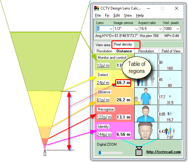
On the Pixel density tab, the Camera view area is divided into regions according to the pixel density (pixels / meter pixels / foot).
The regions are shown as five independent rows in the Table of regions.
The bottom row of the table corresponds to the region closest to the camera, the top row - the most remote region. |
|
On the first column of the table, on the varicolored background rectangles are displayed:
The names of regions and the pixel density values are used according to CCTV Operational Requirements Manual 2009 by default:
|
|
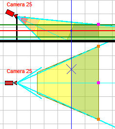
According to the obtained values of the distances you can divide the view area projection by the regions in any graphics program, and thus evaluate the pixel density directly on the site plan.
In VideoCAD program this separation is done automatically. |
|
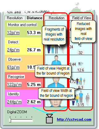
Right, in the Table of regions there are two columns with images:
The Resolution column contains fragments of images with people at the far bounds of each region. These are fragments of images, not whole images. Field of view of the fragments is less than the real field of view, but the resolution of people corresponds the real images exactly.
On the images in the Resolution column, you can see with which resolution people at the far bound of each region will be visible.
The Field of view column contains whole reduced images of people with the field of view at the far bounds of each region. Resolution of these images is less than resolution of the real image, but the field of view corresponds the real images exactly.
On the images in the Field of view column, you can see which part of the field of view people at the far bound of each region will cover.
At the bottom, and left sides of the image the width and height of the field-of-view at the far bound of each region are indicated.
Images in Resolution and Field of view columns are automatically generated according to the pixel density value of each region and camera parameters.
The height of "men in blue shirt" is 2 meters (about 6.5 feet).
|
|
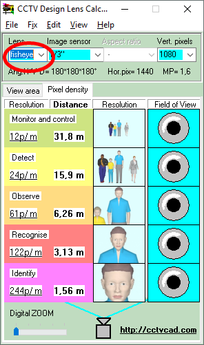
Field of view of panoramic cameras is hemisphere shaped and has a bound in the form of circle. Field of view sizes have no sense for panoramic cameras. Therefore when modeling a panoramic camera in the Field of View column there are fish eyes instead of images.
Test images were taken with a camera with flat field of view (perspective projection), but the field of view of panoramic camera is spherical, so the column Resolution displays pixel resolution corresponds to the expected resolution only at the center of the images. Towards the edges of the images expected resolution of panoramic cameras to be somewhat worse than on the images. |
|
Limitations:
CCTV Design Lens Calculator calculates the pixel density by a simplified way, along the main optical axis of the camera. Height of the camera, camera tilt angle and height of measurements of the pixel density are not taken into account. These parameters are used only for calculating the view area projections.
When modeling resolution only the number of pixels is taken into account. Other factors affecting the detail of object images (compression, lens resolution, contrast, noise, etc.) are not counted. Thus, the models demonstrate the maximum possible image detail of an object with the specified pixel density. The real image of the object may be less detailed.
In modeling pixel density using pictures, the simulated pixel density can not exceed the pixel density of the pictures.
In calculating size of the field of view and pixel density distribution the CCTV Design Lens Calculator does not take into account the lens distortion (except panoramic cameras).
When calculating spatial resolution and modeling images from panoramic cameras, it is assumed that the fish-eye lens has ideal barrel distortion, even distribution of pixels on the field of view in the form of hemisphere and angle of view of 180 degrees.
If necessary, you may consider some of nonregistering factors using corrective factors, or use much more powerful CCTV design software - VideoCAD.
See further: Additional features