CCTV Design Lens Calculator

QUICK START

Hide Navigation Pane

QUICK START

Previous topic Next topic No directory for this topic Expand/collapse all hidden text  

QUICK START

Previous topic Next topic Topic directory requires JavaScript JavaScript is required for expanding text JavaScript is required for the print function Mail us feedback on this topic!  


1. Select measurement system


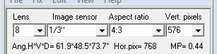
Select measurement system in the Main menu>Help>Measurement system.


2. Specify camera parameters


Lens focal length (Lens) - see camera or lens specification;


Sensor size (Image sensor) - see camera specification;


Aspect ratio - see camera specification;


Vertical number of pixels (Vert. pixels) - see camera specification.


You can choose the parameters from the list or type by keyboard.


See more: Camera parameters


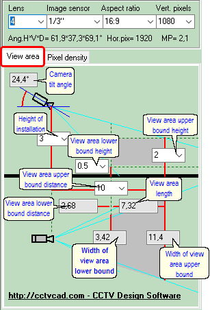
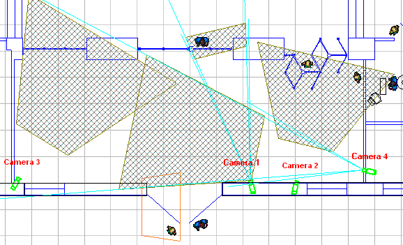
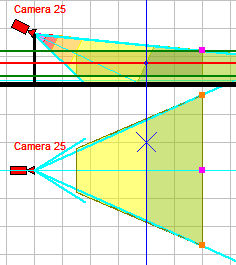
3. Switch to the View area tab and specify camera installation and view area parameters


Specify parameters in the white boxes by choosing them from list or by typing. When any of the parameters is changed, the values of the rest parameters are recalculated.

The parameters in the grey text boxes are results of calculation, you can't set their values directly.


Height of installation - camera installation height;


View area upper bound height - maximal height of surveillance objects;


View area lower bound height- minimal height of surveillance objects;


View area upper bound distance- maximal distance of surveillance*;


The program will calculate the rest parameters of View area projection (grey boxes):


View area lower bound distance - minimal distance of surveillance (dead zone) *;


Width of view area upper bound - width of view area projection at the maximal distance *;


Width of view area lower bound - width of view area projection at the minimal distance *.


* This is correct only for the standard camera position, when Height of installation is more than View area upper bound height.


For other camera positions see: View area tab, View area parameters


According to obtained parameters you can draw the View area projection on the site layout in any graphics program.


Then move the obtained projection on the site plan to get the best camera position.

If necessary, by correcting camera parameters, change the size and shape of the View area projection.


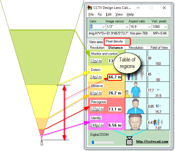
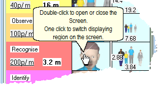
4. Switch to the Pixel density tab


On the Pixel density tab, the Camera view area is divided into regions according to the pixel density (pixels / meter,  pixels / foot).


The regions are shown as five independent rows in the Table of regions.


The bottom row of the table corresponds to the region closest to the camera, the top row - the most remote region.


Each row in the table contains:


Name of region;


Pixel density value at the far bound of region (pixel/meter, pixel/foot);


Distance along the main optical axis up to the far bound of region;


Two images: Resolution and Field of View.


On the images in the Resolution column, you can see with which resolution people at the far bound of each region will be visible.


On the images in the Field of view column, you can see which part of the field of view people at the far bound of each region will cover.


At the bottom, and left sides of the image the width and height of the field-of-view at the far bound of each region are indicated.


According to the obtained values ​​of the distances you can divide the view area projection by the regions in any graphics program, and thus evaluate the pixel density directly on the site plan.


See more: Pixel density tab


5. Screen


Images on the Table of regions are small, so you can quickly evaluate the Pixel density and the Field-of-view sizes at several distances simultaneously.

In addition, it is possible to show any image in any size for more detailed consideration.

For this purpose there is a separate scalable window -  the Screen.


The Screen can be opened in several ways: by Main Menu>View>Screen, using the same name item of pop-up menu of Table of regions.


The Screen can be opened with the simultaneous show images of any region by double clicking on any image in the corresponding row of the Table of regions.


You can switch displaying region on the Screen by clicking on the appropriate row in the Table of regions or by selecting the name of region in Current region combo-box on the Screen.


See more: Screen


6. Limitations


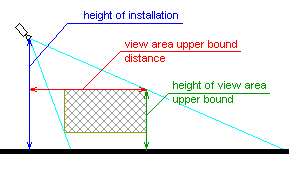
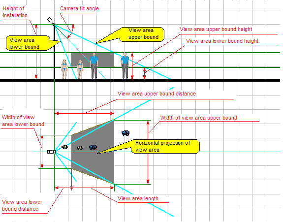
CCTV Design Lens Calculator calculates the pixel density by a simplified way, along the main optical axis of the camera. Height of the camera, camera tilt angle and height of measurements of the pixel density are not taken into account. These parameters are used only for calculating the view area projections.


When modeling resolution only the number of pixels is taken into account. Other factors affecting the detail of object images (compression, lens resolution, contrast, noise, etc.) are not counted.  Thus, the models demonstrate the maximum possible image detail of an object with the specified pixel density. The real image of the object may be less detailed.


In modeling pixel density using pictures, the simulated pixel density can not exceed the pixel density of the pictures.


If necessary, you may consider some of nonregistering factors using corrective factors, or use much more powerful CCTV design software - VideoCAD.