|
Example 5 Measuring lens aperture |
  
|
|
Example 5 Measuring lens aperture |
|
Amount of the light, going through the lens, is determined by the lens aperture. The aperture is indicated as F-number. For example: F1.2, F1.4, F2.0…
The larger F-number is, the less light goes through the lens.
As a rule, the bigger entrance pupil of the lens is, the more light it transmits. Pin-hole lens have the narrowest aperture (larger value of F-number).
The aperture of auto iris lenses increases maximally (F-number value decreases) in low light conditions. For such lens instead of aperture, the maximum and minimum apertures are indicated, for example F1.2- F360.
Lens optical transmission changes inversely as the square of F-number.
For example, the lens F1.0 transmits in 4 times more light, than F2.0.
The F number is always indicated in the specification of lens, but as is the case with cameras, the specification's values and real ones can be not equal. Measurement is necessary to know the aperture of varifocal lens or ZOOM lens for a specified focal length. Aperture of such lenses depends on the current focal length, but only one value of the F number is indicated in the specification.
Problem
There is a lens. It is necessary to measure its aperture (F- number).
Equipment:
| • | Luxmeter (a device for measuring illumination). Almost any kind of such a device with standard CIE spectral response will suit. |
| • | A sample lens with known aperture with focal length close to the focal length of the lens under test and with the same type of mounting. |
| • | Camera with sensitivity 1..3lx preferably with the possibility to switch off AGC. The camera must have the same mounting type. It can be an analog or IP camera. |
| • | In case of using an analog camera, it is needed any PC-based video capture system, TV-tuner with video input, etc. The System should allow to display live video on the computer screen without compression or with little compression. |
In case of using IP camera it is enough to have possibility to display images on the screen.
| • | Compact tungsten halogen lamp 12V, 10W. |
| • | Stabilized power supply unit for the lamp. 12V DC, without considerable ripples of output voltage. |
| • | A sheet of white paper (A4 format). |
| • | Stand. It is recommended for convenience and accuracy. |
| • | Measuring aperture should be carried out in a dark room. |
Order of work
1. Switch off all image processing and AGC in the camera.
AGC switching off increases measure accuracy and allows working with illumination of 5..10lx, even if the camera has sensitivity of 0.2..1lx.
2. Mount the sample lens on the camera, mount the camera on stand, direct it towards sheet of paper, connect to computer, display image on the screen.
3. In the camera field-of-view place the luxmeter sensor.
|
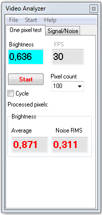
4. Run Video Analyzer. Switch to the One pixel test tab. Mark Cycle box, click Start. After that move fast the mouse cursor to the center of white paper on the screen, close to the sensor window.
5. Switch on tungsten halogen lamp. Switch off common light.
6. By changing distance from the lamp to the sheet of paper, obtain that the Brightness>Average measured by the Video analyzer would be equal to 0.22-0.25 after finishing measuring cycle by 100 frames.
Objects on the image should be visible.
You must not change the lamp supply voltage. It should be equal to nominal lamp supply voltage. Change Illumination only be means of distance variation between the lamp and the sheet of paper. Be sure, that the luxmeter sensor window and the place of cursor on the sheet of paper have visually equal illumination.
7. Write down luxmeter reading and the Brightness>Average value according to the Video analyzer reading with the sample lens. |
8. Mount the lens under test to the camera.
9. By changing the distance from the lamp to the sheet of paper, obtain equal with step 7 value of Brightness>Average after finishing measuring cycle by 100 frames.
You must not change the lamp supply voltage. It should be equal to nominal lamp supply voltage. Change Illumination only be means of distance variation between the lamp and the sheet of paper.
10. Write down the luxmeter reading with the lens under test.
11. Calculate the F- number of the lens under test according the formula:
Ft=Fs*√(Et/Es);
where:
| • | Ft - F number of the lens under test; |
| • | Fs - F number of the sample lens; |
| • | Es - luminance, measured with the sample lens (step 7); |
| • | Et - luminance, measured with the lens under test (step 10); |
| • | character √ - root of number. |
See also: Example 3 Measuring low illumination. Calibration of lenses and filters.
See also: Illumination and camera sensitivity in CCTV.