CCTV
Focus (Russian edition) #5-2004
Professional
design of CCTV systems
During
the design of CCTV systems much time is spent on estimating
lens focal length and the right location of video cameras to
get the necessary image on the screen.
Estimating person identification areas and license plate reading
areas causes additional difficulties for a designer. The task
becomes more complicated when it is necessary to choose optimal
relative positions of several cameras or when it is necessary
to make one camera solve several tasks (for example identification
of entering people and surveillance over the perimeter). You
can also add the necessity to calculate how this or that object
will be displayed, where the motion detector will detect a person
for an instance with enough light and contrast ratio, and where
it will not.
Not
only lens focal length but also the height of the camera installation,
maximum distance and the height of surveillance have an influence
on the screen image. Choosing the wrong camera location and the
wrong height of camera installation, even with the replacement
of the lens, wouldn’t be able to provide you with the desired
image!
If we also remember obstacles that distort the viewing areas
and dead space under the camera, then we can see the difficulty
of the problem. The more difficult the task is the more likely
that a mistake will occur. The result of which at best can be
a project cost increase.
These tasks can be solved in different ways.
Someone accurately calculates the viewing areas for several
heights and lens focal length of each camera using self deducted
formulas or formulas taken from guide books and then transfers
or combines obtained templates.
Someone makes the calculation easier and having introduced reserves
gets approximate results with the help of a Lens calculator.
Someone draws on the plans only the horizontal angles from lens
specifications thus confusing himself and the customer even
more.
And many people ignore such calculations because of their complexity
and labour-intensiveness and place wide-angle lenses or the
most expensive ones (from the price list of the producer).
A
CCTV project that doesn’t show the viewing areas of each
camera and their functions in different regions of space cannot
be considered a professional one.
Wide-angle
lenses (very often they remain the same even after acceptance
of work) as a rule satisfy the needs of a customer only up to
the first emergency. After an emergency it comes out that there
is practically no use for the installed CCTV system. Criminal
is not identified, license plate is not read out, motion detector
did not detect any movement. It becomes obvious that there should
be more cameras, their locations should be different and lenses
should have other focal lengths.
The
situation looks different if professionally (well) executed
CCTV projects participate in a tender. Using a professional
CCTV project it is possible to discuss with a customer a task
for each camera, and to choose and substantiate the necessary
number. After doing the calculations more video cameras may
not be needed as one camera can fulfill several tasks. Such
solutions are more time consuming but create effective and at
the same time economical projects. After each discussion and
transference and when camera parameters change one has to recalculate
and compare several variants of cameras placement. Thus professional
designing of a television system is a very difficult task that
demands much time.
Not all customers understand this and they give preference not
to the best project, but to the one that was quickly rendered
or to the cheapest one.
All
dependences of camera viewing areas obey the laws of geometrical
optics and can be described mathematically.
Widely spread are Lens Calculators that can be used on many
security web sites on-line. They can be in the form of small
programs or a plastic circle. Viewing areas are viewed as a
rule in the two-dimensional aspect which allows the use of relatively
easy calculations.
Calculators’ resources are approximately the same but
they are insufficient for professional designing. The most convenient
is the plastic circle which can be easily used in field conditions.
Calculators are convenient for rapid calculations of viewing
field width and height, but they don’t allow calculating
even the dead space under the video camera let alone full-fledged
calculation of viewing areas’ projections to draw them
on the plan. This makes calculation of person identification
areas and license plate reading areas out of the question.
Moving
to a three dimension coordinate system the complexity of calculations
increases many times, and it is practically impossible to find
a good three-dimensional free calculator. But it is still inconvenient
to work with a specialized three-dimensional calculator especially
when it is necessary to calculate several connected video cameras.
One has to simultaneously use a program-calculator and CAD program,
that locates video cameras on the plan, while recalculating
and redrawing viewing areas projections in order to get the
necessary result.
The next step is the integration of a three-dimension calculator
and CAD program. The calculator acquires a graphical interface
and its calculation results are presented in graphic form. Obtained
graphical calculation results are represented directly on the
plan of an object in horizontal and vertical projections.
Graphical interface that allows locating video cameras by one
mouse click, to raise or lower a video camera only by one turn
of a mouse wheel, change its angle of inclination and lens focal
length and see the result there and then, makes CCTV systems
designing easy and exciting work. Completed projects have the
maximum of exactness, are quick to implement and correct and
don’t demand from a CCTV systems designer mathematical
knowledge and understanding of peculiarities of objects’
representation in different parts of viewing areas (although
such understanding remains rather useful).
These
and very many other ideas are realized in full measure in a
new program intended for CCTV systems designing. This program
is called VideoCAD. The latest version of VideoCAD 5.0 is a
full value CAD program integrated with a special three-dimension
calculator for calculating cameras’ viewing areas’
parameters. With the help of VideoCAD one can design a CCTV
project of any difficulty in a short period of time. Specialized
calculations of video surveillance (viewing areas, person identification
areas, license reading-out areas, detailed representation of
objects in different parts of a viewing area, calculation of
length and electrical parameters of cables) are tightly integrated
with traditional CAD interface.
Let’s look briefly at an example of designing
a CCTV system with the help of VideoCAD.
1. Examining an object, discussing and formulating the list
of tasks stated before the CCTV system. Getting of an object
plan (better in electronic version, but also acceptable on paper).
2. Object plan drawn on paper can be scanned and used in VideoCAD
as a background for cameras location. Electronic object plan
can be also used in VideoCAD (*.bmp, *.jpg, *.jpeg, *.emf, *.wmf,
*.dxf, *.dwg are supported).
3. Direct on the background with the help of VideoCAD one can
create preliminary camera locations.
4. During the next visit on the object preliminary cameras location
is corrected taking into account possible camera locations,
light, different obstacles, possibilities of cables lay out,
etc. Corrections of location are simple and convenient in VideoCAD.
All necessary actions are conducted with several mouse clicks.
5. With the help of VideoCAD length and necessary parameters
of coaxial and power cables can be calculated. File containing
text with detailed descriptions of all video cameras and cables
is produced. On basis of obtained location with marked viewing
areas and also with the help of the text file a business proposal
is made.
6. Business proposal is sent to the customer for discussion
and concordance. During the discussion camera tasks and their
locations are specified after which with joint efforts requirements
specification is made. While making requirements specification
one can also use the text file. Especially efficient is the
discussion of a project in front of the computer, as then it
is easy to choose and total the required number of cameras.
It is obvious that after such a dialog a competent customer
will hardly move to a competitor.
7. In the process of designing all that is left, if necessary,
is to draw out the planning in VideoCAD, to make specifications,
explanatory notes, estimate calculations, etc. Your professional
project is ready!
8. While installing and adjusting, installers won’t have
to think about how to turn and to incline each camera. In the
project everything they need will be mentioned; lens focal length,
place and height of each camera, viewing area. An installer
will only need to turn the camera in order to get the designated
project viewing area.
9. While accepting the CCTV system, the customer makes sure
that all viewing areas agree with those marked in the project.
After estimating the quality of image and installation work,
he signs acceptance report.
10. After having accepted the system, all changes to viewing
areas should be charged extra.
Of
course the real sequence of actions can differ, but in general
one can see, that the process of designing a CCTV system is
getting clearer for both the designer and the customer. The
most important is the result one gets; an efficient CCTV system
that fulfills its functions in full measure. Who knows how many
crimes can be prevented and uncovered with the help of it.
With
VideoCAD you can:
Choose
the most suitable lenses, heights and locations for camera installation
to provide the required parameters of view areas, detect and
identify a person, read license plates and obtain an object
image of required size on the screen using the known actual
sizes and location of the object.
Choose visually a relative location of cameras using the graphics
window with CAD interface.
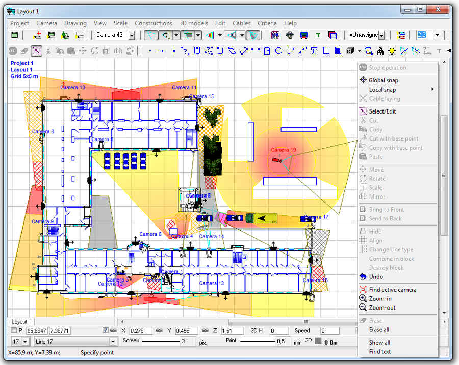
Calculate the horizontal projection sizes of viewing, person
detecting, identifying and license plate reading areas to draw
them on the object plan.
Measure the view area distortions, arising from natural obstacles.
Construct
three dimensional models of real scenes with the possibility
of loading prepared 3D models (a person, a car, etc., this library
can be enlarged).
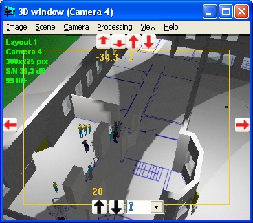
Obtain a model of a real image from each video camera. This
image can be printed and saved.
Model
quality parameters of a video image (resolution, compression,
coloration, smoothing, contrast, brightness).
Calculate the image size on the screen of any object in camera
view area in the percentage of screen size, pixels, TV lines
and millimeters (inches in case of Imperial format).
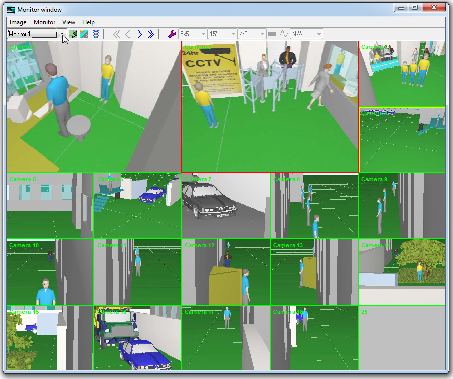
Model
multiscreen monitors and design operator interface using the
Monitors window.
Locate cameras and cables on the prepared layouts in *.bmp,
*.jpg, *.emf, *.wmf, *.dwg, *.dxf formats.
Obtain a drawing containing two projections of object layout
with the camera images, calculated view areas and cables, and
with coordinate grid and titles to be pasted into graphical
path of the project.
Print out the obtained drawing on one or several pages.It is
possible to use prepared frames with standard overlay Title-Block
and logo.
Export
the obtained drawing into any of the following formats: *.bmp,*.emf,
*.wmf, *.dxf (R14),*.dxf (R2000).
Calculate the Depth-of-field of each camera in the project.
Obtain a text file with full description of all the cameras
in the project, view areas and cables to be pasted into a project
explanatory note or used as an instruction for installation.
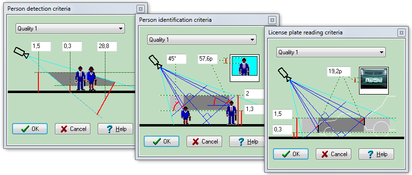
Study
the influence of the criteria of person detection, identification
and license plate reading on the sizes and location of the correspondent
areas by changing the criteria according to the video image
quality.
Study the principles of object representation in different view
area parts using the test object and the graphics window.
Calculate the length and electric parameters of cables.
Save expenses and win tenders due to the reduction of cameras'
quantity in projects and the increase of their efficiency.
Reduce the time expended and boost the design quality.
Cut down the amount of controversial situations with customers
and accelerate their solution.
All
the calculations are real-time allowing to view the influence
of each parameter specified upon the final result.
VideoCAD does not use any simplified formulas and techniques,
in non-typical situations giving out considerable errors.
VideoCAD operates with any correct parameters, both selected
from the list or typed.
VideoCAD can be used for the prompt, but exact calculations
of the view area projections to draw on a location plan when
performing a graphical part of project. It can be also used
to perform a view area scrupulous analysis to choose the most
suitable camera location and lens parameters.
VideoCAD
can be effective at CCTV designer training.
Despite
its reach of opportunities VideoCAD is an inexpensive program,
available even for the general public. At present VideoCAD is
successfully used in many CCTV projects of different scales.